Network > Interfaces
208
SonicOS 5.8.1 Administrator Guide
Internal Security
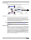
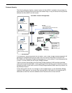
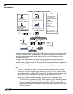
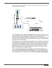
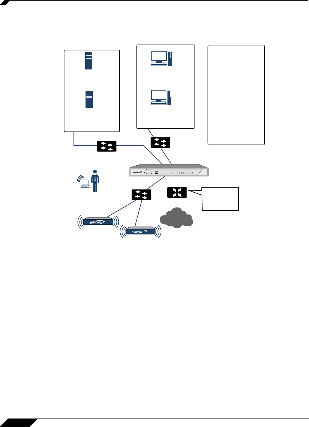
This diagram depicts a network where the SonicWALL will act as the perimeter security device
and secure wireless platform. Simultaneously, it will provide L2 Bridge security between the
workstation and server segments of the network without having to readdress any of the
workstation or servers.
This typical inter-departmental Mixed Mode topology deployment demonstrates how the
SonicWALL can simultaneously Bridge and route/NAT. Traffic to/from the Primary Bridge
Interface (Server) segment from/to the Secondary Bridge Interface (Workstation) segment will
pass through the L2 Bridge.
Since both interfaces of the Bridge-Pair are assigned to a Trusted (LAN) zone, the following will
apply:
• All traffic will be allowed by default, but Access Rules could be constructed as needed.
Consider, for the point of contrast, what would
occur if the X2 (Primary Bridge Interface)
was instead assigned to a Public (DMZ) zone: All the Workstations would be able to reach
the Servers, but the Servers would not be able to initiate communications to the
Workstations. While this would probably support the traffic flow requirements (i.e.
Workstations initiating sessions to Servers), it would have two undesirable effects:
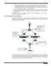
a. The DHCP server would be in the DMZ. DHCP requests from the Workstations would
pass through the L2 Bridge to the DHCP server (192.168.0.100), but the DHCP offers
from the server would be dropped by the default DMZ->LAN Deny Access Rule. An
Access Rule would have to be added, or the default modified, to allow this traffic from
the DMZ to the LAN.
WorkStation
IP=192.168.0.200/24
GW=192.168.0.1
MAC=00:11:22:33:44:55
Workstation
IP=192.168.0.200/24
GW=192.168.0.1
MAC=00:11:55:66:77:88
LAN 192.168.0.x/24
SonicWALL Firewall Mixed L2 Bridge Mode
Mail & DHCP Server
IP=192.168.0.100/24
GW=192.168.0.1
MAC=00:AA:BB:CC:DD:EE
File Server
IP=192.168.0.101/24
GW=192.168.0.1
MAC=00:CC:AA:BB:EE:EE
Switch
LAN 192.168.0.x/24
Wireless Client
IP= 172.16.31.100
Switch
Router
Internet
X0
X1
X2
X3
X0 (LAN)
IP=Secondary Bridge
Interface to X2
MAC= 00:06:B1:10:10:10
KEY
X1 (WAN)
IP= 10.0.012/24
MAC= 00:06:B1:10:10:11
GW= 10.0.0.1
X2 (LAN)
IP= 192.168.0.1/24
MAC= 00:06:B1:10:10:12
X3 (WLAN)
IP= 172.16.31.1/24
MAC= 00:06:B1:10:10:13
Switch
Interface e0
IP=10.0.01
Interface s0
ISP assigned
link/spd
pc card lanwan opt 1 2 3 4
5 6
signal
link/act
activity
NSA 240
NSA 2400


