


Appendix A Electrical Characteristics
MC9S12XDP512 Data Sheet, Rev. 2.11
Freescale Semiconductor 925
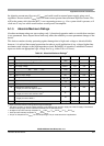
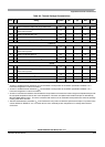
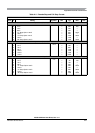
Table A-5. Thermal Package Characteristics
1
1
The values for thermal resistance are achieved by package simulations
Num C Rating Symbol Min Typ Max Unit
LQFP144
1 T Thermal resistance LQFP144, single sided PCB
2
θ
JA
——41°C/W
2 T Thermal resistance LQFP144, double sided PCB
with 2 internal planes
3
θ
JA
——32°C/W
3 Junction to Board LQFP 144 θ
JB
——22°C/W
4 Junction to Case LQFP 144
4
θ
JC
— — 7.4 °C/W
5 Junction to Package Top LQFP144
5
Ψ
JT
—— 3°C/W
LQFP112
6 T Thermal resistance LQFP112, single sided PCB
2
2
Junction to ambient thermal resistance, θ
JA
was simulated to be equivalent to the JEDEC specification JESD51-2 in a
horizontal configuration in natural convection.
θ
JA
——43°C/W
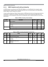
7 T Thermal resistance LQFP112, double sided PCB
with 2 internal planes
3
3
Junction to ambient thermal resistance, θ
JA
was simulated to be equivalent to the JEDEC specification JESD51-7 in a
horizontal configuration in natural convection.
θ
JA
——32°C/W
8 Junction to Board LQFP112 θ
JB
——22°C/W
9 Junction to Case LQFP112
4
θ
JC
—— 7°C/W
10 Junction to Package Top LQFP112
5
Ψ
JT
—— 3°C/W
QFP80
11 T Thermal resistance QFP 80, single sided PCB
2
θ
JA
——45°C/W
12 T Thermal resistance QFP 80, double sided PCB
with 2 internal planes
3
θ
JA
——33°C/W
13 T Junction to Board QFP 80 θ
JB
——19°C/W
14 T Junction to Case QFP 80
4
4
Junction to case thermal resistance was simulated to be equivalent to the measured values using the cold plate technique with
the cold plate temperature used as the “case” temperature. This basic cold plate measurement technique is described by
MIL-STD 883D, Method 1012.1. This is the correct thermal metric to use to calculate thermal performance when the package
is being used with a heat sink.
θ
JC
——11°C/W
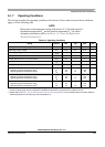
15 T Junction to Package Top QFP 80
5
5
Thermal characterization parameter Ψ
JT
is the “resistance” from junction to reference point thermocouple on top center of the
case as defined in JESD51-2. Ψ
JT
is a useful value to use to estimate junction temperature in a steady state customer
enviroment.
Ψ
JT
—— 3°C/W