


Chapter 16 Serial Peripheral Interface (S12SPIV4)
MC9S12XDP512 Data Sheet, Rev. 2.11
730 Freescale Semiconductor
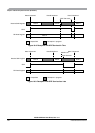
16.4.4 SPI Baud Rate Generation
Baud rate generation consists of a series of divider stages. Six bits in the SPI baud rate register (SPPR2,
SPPR1, SPPR0, SPR2, SPR1, and SPR0) determine the divisor to the SPI module clock which results in
the SPI baud rate.
The SPI clock rate is determined by the product of the value in the baud rate preselection bits
(SPPR2–SPPR0) and the value in the baud rate selection bits (SPR2–SPR0). The module clock divisor
equation is shown in Equation 16-3.
BaudRateDivisor = (SPPR + 1) • 2
(SPR + 1)
Eqn. 16-3
When all bits are clear (the default condition), the SPI module clock is divided by 2. When the selection
bits (SPR2–SPR0) are 001 and the preselection bits (SPPR2–SPPR0) are 000, the module clock divisor
becomes 4. When the selection bits are 010, the module clock divisor becomes 8, etc.
When the preselection bits are 001, the divisor determined by the selection bits is multiplied by 2. When
the preselection bits are 010, the divisor is multiplied by 3, etc. See Table 16-7 for baud rate calculations
for all bit conditions, based on a 25 MHz bus clock. The two sets of selects allows the clock to be divided
by a non-power of two to achieve other baud rates such as divide by 6, divide by 10, etc.
The baud rate generator is activated only when the SPI is in master mode and a serial transfer is taking
place. In the other cases, the divider is disabled to decrease I
DD
current.
NOTE
For maximum allowed baud rates, please refer to the SPI Electrical
Specification in the Electricals chapter of this data sheet.
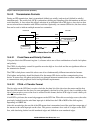
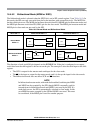
16.4.5 Special Features
16.4.5.1 SS Output
The SS output feature automatically drives the SS pin low during transmission to select external devices
and drives it high during idle to deselect external devices. When
SS output is selected, the SS output pin
is connected to the
SS input pin of the external device.
The SS output is available only in master mode during normal SPI operation by asserting SSOE and
MODFEN bit as shown in Table 16-3.
The mode fault feature is disabled while
SS output is enabled.
NOTE
Care must be taken when using the
SS output feature in a multimaster
system because the mode fault feature is not available for detecting system
errors between masters.