


Chapter 16 Serial Peripheral Interface (S12SPIV4)
MC9S12XDP512 Data Sheet, Rev. 2.11
Freescale Semiconductor 731
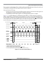
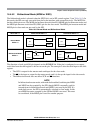
16.4.5.2 Bidirectional Mode (MOMI or SISO)
The bidirectional mode is selected when the SPC0 bit is set in SPI control register 2 (see Table 16-9). In
this mode, the SPI uses only one serial data pin for the interface with external device(s). The MSTR bit
decides which pin to use. The MOSI pin becomes the serial data I/O (MOMI) pin for the master mode, and
the MISO pin becomes serial data I/O (SISO) pin for the slave mode. The MISO pin in master mode and
MOSI pin in slave mode are not used by the SPI.
The direction of each serial I/O pin depends on the BIDIROE bit. If the pin is configured as an output,
serial data from the shift register is driven out on the pin. The same pin is also the serial input to the shift
register.
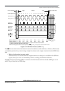
• The SCK is output for the master mode and input for the slave mode.
• The
SS is the input or output for the master mode, and it is always the input for the slave mode.
• The bidirectional mode does not affect SCK and
SS functions.
NOTE
In bidirectional master mode, with mode fault enabled, both data pins MISO
and MOSI can be occupied by the SPI, though MOSI is normally used for
transmissions in bidirectional mode and MISO is not used by the SPI. If a
mode fault occurs, the SPI is automatically switched to slave mode. In this
case MISO becomes occupied by the SPI and MOSI is not used. This must
be considered, if the MISO pin is used for another purpose.
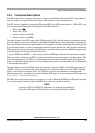
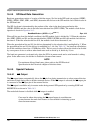
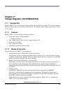
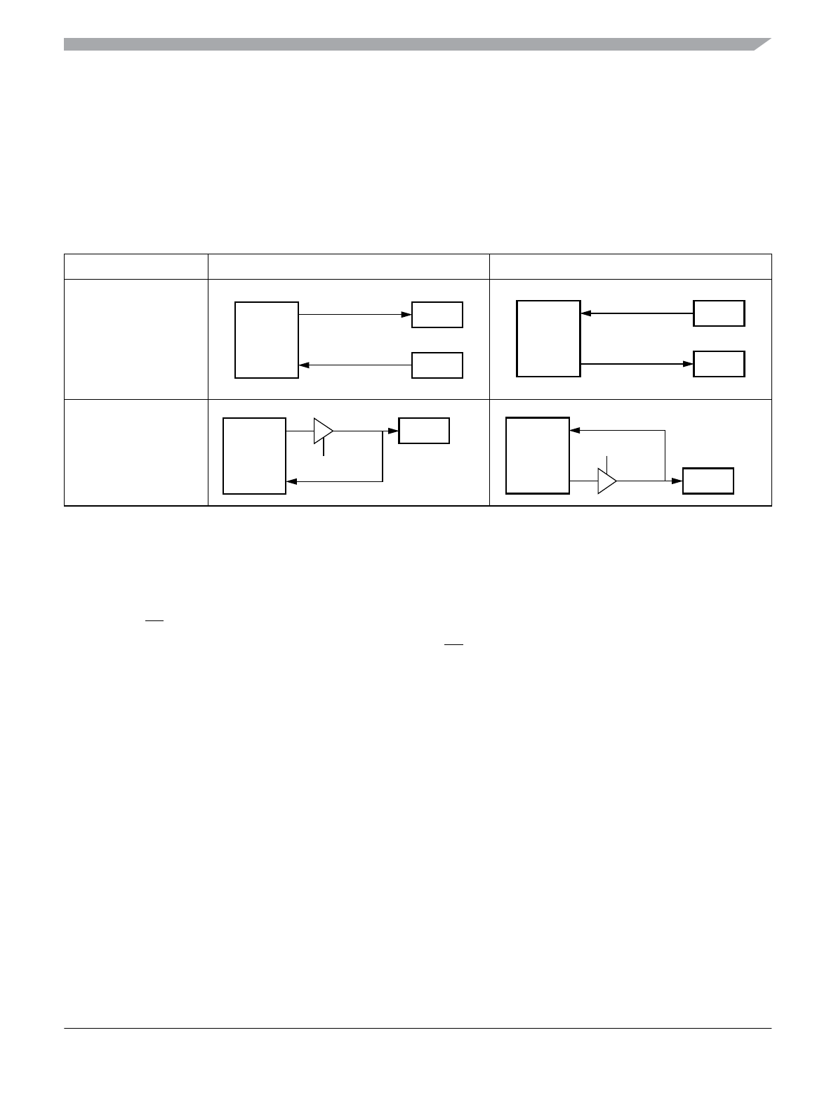
Table 16-9. Normal Mode and Bidirectional Mode
When SPE = 1 Master Mode MSTR = 1 Slave Mode MSTR = 0
Normal Mode
SPC0 = 0
Bidirectional Mode
SPC0 = 1
SPI
MOSI
MISO
Serial Out
Serial In
SPI
MOSI
MISO
Serial In
Serial Out
SPI
MOMI
Serial Out
Serial In
BIDIROE
SPI
SISO
Serial In
Serial Out
BIDIROE