


Chapter 12 Pulse-Width Modulator (S12PWM8B8CV1)
MC9S12XDP512 Data Sheet, Rev. 2.11
590 Freescale Semiconductor
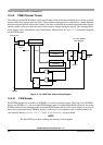
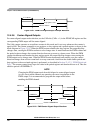
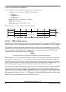
Either left aligned or center aligned output mode can be used in concatenated mode and is controlled by
the low order CAEx bit. The high order CAEx bit has no effect.
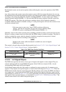
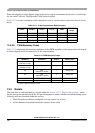
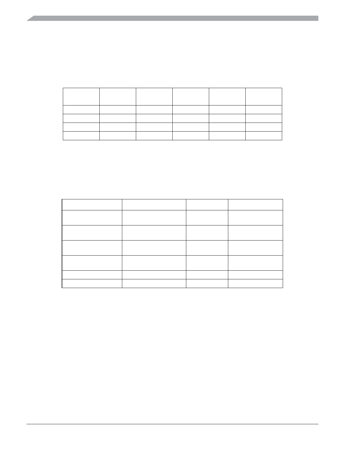
Table 12-11 is used to summarize which channels are used to set the various control bits when in 16-bit
mode.
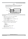
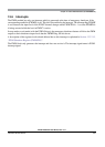
12.4.2.8 PWM Boundary Cases
Table 12-12 summarizes the boundary conditions for the PWM regardless of the output mode (left aligned
or center aligned) and 8-bit (normal) or 16-bit (concatenation).
12.5 Resets
The reset state of each individual bit is listed within the Section 12.3.2, “Register Descriptions” which
details the registers and their bit-fields. All special functions or modes which are initialized during or just
following reset are described within this section.
• The 8-bit up/down counter is configured as an up counter out of reset.
• All the channels are disabled and all the counters do not count.
Table 12-11. 16-bit Concatenation Mode Summary
CONxx PWMEx PPOLx PCLKx CAEx
PWMx
Output
CON67 PWME7 PPOL7 PCLK7 CAE7 PWM7
CON45 PWME5 PPOL5 PCLK5 CAE5 PWM5
CON23 PWME3 PPOL3 PCLK3 CAE3 PWM3
CON01 PWME1 PPOL1 PCLK1 CAE1 PWM1
Table 12-12. PWM Boundary Cases
PWMDTYx PWMPERx PPOLx PWMx Output
$00
(indicates no duty)
>$00 1 Always low
$00
(indicates no duty)
>$00 0 Always high
XX $00
1
(indicates no period)
1
Counter = $00 and does not count.
1 Always high
XX $00
1
(indicates no period)
0 Always low
>= PWMPERx XX 1 Always high
>= PWMPERx XX 0 Always low