


Appendix A Electrical Characteristics
MC9S12XDP512 Data Sheet, Rev. 2.11
920 Freescale Semiconductor
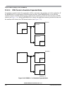
V
SS1
and V
SS2
are internally connected by metal.
V
DDA
, V
DDX
, V
DDR
as well as V
SSA
, V
SSX
, V
SSR
are connected by anti-parallel diodes for ESD
protection.
NOTE
In the following context V
DD35
is used for either V
DDA
,V
DDR
, and V
DDX
;
V
SS35
is used for either V
SSA
, V
SSR
and V
SSX
unless otherwise noted.
I
DD35
denotes the sum of the currents flowing into the V
DDA
, V
DDX
and
V
DDR
pins.
V
DD
is used for V
DD1
,V
DD2
and V
DDPLL
,V
SS
is used for V
SS1
,V
SS2
and
V
SSPLL
.
I
DD
is used for the sum of the currents flowing into V
DD1
and V
DD2
.
A.1.3 Pins
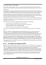
There are four groups of functional pins.
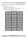
A.1.3.1 I/O Pins
Those I/O pins have a nominal level in the range of 3.15 V to 5.5 V. This class of pins is comprised of all
port I/O pins, the analog inputs, BKGD and the
RESET pins.The internal structure of all those pins is
identical; however, some of the functionality may be disabled. For example, for the analog inputs the
output drivers, pull-up and pull-down resistors are disabled permanently.
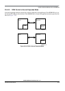
A.1.3.2 Analog Reference
This group is made up by the V
RH
and V
RL
pins.
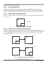
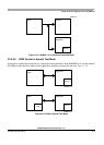
A.1.3.3 Oscillator
The pins XFC, EXTAL, XTAL dedicated to the oscillator have a nominal 2.5 V level. They are supplied
by V
DDPLL
.
A.1.3.4 TEST
This pin is used for production testing only.
A.1.3.5 V
REGEN
This pin is used to enable the on-chip voltage regulator.
A.1.4 Current Injection
Power supply must maintain regulation within operating V
DD35
or V
DD
range during instantaneous and
operating maximum current conditions. If positive injection current (V
in
> V
DD35
) is greater than I
DD35
,