


Chapter 14 Freescale’s Scalable Controller Area Network (S12MSCANV3)
MC9S12XDP512 Data Sheet, Rev. 2.11
622 Freescale Semiconductor
14.3.2 Register Descriptions
This section describes in detail all the registers and register bits in the MSCAN module. Each description
includes a standard register diagram with an associated figure number. Details of register bit and field
function follow the register diagrams, in bit order. All bits of all registers in this module are completely
synchronous to internal clocks during a register read.
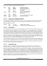
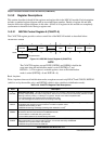
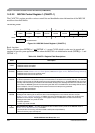
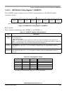
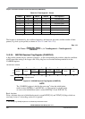
14.3.2.1 MSCAN Control Register 0 (CANCTL0)
The CANCTL0 register provides various control bits of the MSCAN module as described below.
NOTE
The CANCTL0 register, except WUPE, INITRQ, and SLPRQ, is held in the
reset state when the initialization mode is active (INITRQ = 1 and
INITAK = 1). This register is writable again as soon as the initialization
mode is exited (INITRQ = 0 and INITAK = 0).
Read: Anytime
Write: Anytime when out of initialization mode; exceptions are read-only RXACT and SYNCH, RXFRM
(which is set by the module only), and INITRQ (which is also writable in initialization mode).
Module Base + 0x0000
76543210
R
RXFRM
RXACT
CSWAI
SYNCH
TIME WUPE SLPRQ INITRQ
W
Reset: 00000001
= Unimplemented
Figure 14-3. MSCAN Control Register 0 (CANCTL0)
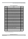
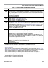
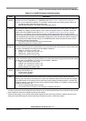
Table 14-2. CANCTL0 Register Field Descriptions
Field Description
7
RXFRM
1
Received Frame Flag — This bit is read and clear only. It is set when a receiver has received a valid message
correctly, independently of the filter configuration. After it is set, it remains set until cleared by software or reset.
Clearing is done by writing a 1. Writing a 0 is ignored. This bit is not valid in loopback mode.
0 No valid message was received since last clearing this flag
1 A valid message was received since last clearing of this flag
6
RXACT
Receiver Active Status — This read-only flag indicates the MSCAN is receiving a message. The flag is
controlled by the receiver front end. This bit is not valid in loopback mode.
0 MSCAN is transmitting or idle
2
1 MSCAN is receiving a message (including when arbitration is lost)
2
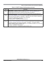
5
CSWAI
3
CAN Stops in Wait Mode — Enabling this bit allows for lower power consumption in wait mode by disabling all
the clocks at the CPU bus interface to the MSCAN module.
0 The module is not affected during wait mode
1 The module ceases to be clocked during wait mode
4
SYNCH
Synchronized Status — This read-only flag indicates whether the MSCAN is synchronized to the CAN bus and
able to participate in the communication process. It is set and cleared by the MSCAN.
0 MSCAN is not synchronized to the CAN bus
1 MSCAN is synchronized to the CAN bus