


Chapter 8 Analog-to-Digital Converter (ATD10B8CV3)
MC9S12XDP512 Data Sheet, Rev. 2.11
364 Freescale Semiconductor
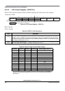
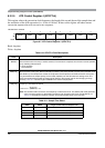
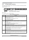
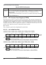
8.3.2.7 ATD Status Register 0 (ATDSTAT0)
This read-only register contains the sequence complete flag, overrun flags for external trigger and FIFO
mode, and the conversion counter.
Read: Anytime
Write: Anytime (No effect on (CC2, CC1, CC0))
Module Base + 0x0006
76543210
R
SCF
0
ETORF FIFOR
0 CC2 CC1 CC0
W
Reset 00000000
= Unimplemented or Reserved
Figure 8-9. ATD Status Register 0 (ATDSTAT0)
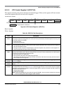
Table 8-17. ATDSTAT0 Field Descriptions
Field Description
7
SCF
Sequence Complete Flag — This flag is set upon completion of a conversion sequence. If conversion
sequences are continuously performed (SCAN = 1), the flag is set after each one is completed. This flag is
cleared when one of the following occurs:
A) Write “1” to SCF
B) Write to ATDCTL5 (a new conversion sequence is started)
C) If AFFC=1 and read of a result register
0 Conversion sequence not completed
1 Conversion sequence has completed
5
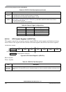
ETORF
External Trigger Overrun Flag — While in edge trigger mode (ETRIGLE = 0), if additional active edges are
detected while a conversion sequence is in process the overrun flag is set. This flag is cleared when one of the
following occurs:
A) Write “1” to ETORF
B) Write to ATDCTL2, ATDCTL3 or ATDCTL4 (a conversion sequence is aborted)
C) Write to ATDCTL5 (a new conversion sequence is started)
0 No External trigger over run error has occurred
1 External trigger over run error has occurred
4
FIFOR
FIFO Over Run Flag — This bit indicates that a result register has been written to before its associated
conversion complete flag (CCF) has been cleared. This flag is most useful when using the FIFO mode because
the flag potentially indicates that result registers are out of sync with the input channels. However, it is also
practical for non-FIFO modes, and indicates that a result register has been over written before it has been read
(i.e., the old data has been lost). This flag is cleared when one of the following occurs:
A) Write “1” to FIFOR
B) Start a new conversion sequence (write to ATDCTL5 or external trigger)
0 No over run has occurred
1 An over run condition exists
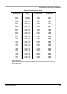
2–0
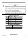
CC[2:0]
Conversion Counter — These 3 read-only bits are the binary value of the conversion counter. The conversion
counter points to the result register that will receive the result of the current conversion. E.g. CC2 = 1, CC1 = 1,
CC0 = 0 indicates that the result of the current conversion will be in ATD result register 6. If in non-FIFO mode
(FIFO = 0) the conversion counter is initialized to zero at the begin and end of the conversion sequence. If in
FIFO mode (FIFO = 1) the register counter is not initialized. The conversion counters wraps around when its
maximum value is reached.