


Chapter 16 Serial Peripheral Interface (S12SPIV4)
MC9S12XDP512 Data Sheet, Rev. 2.11
716 Freescale Semiconductor
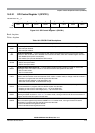
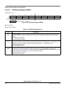
16.3.2.2 SPI Control Register 2 (SPICR2)
Read: Anytime
Write: Anytime; writes to the reserved bits have no effect
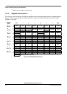
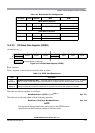
Table 16-3. SS Input / Output Selection
MODFEN SSOE Master Mode Slave Mode
00
SS not used by SPI SS input
01
SS not used by SPI SS input
10
SS input with MODF feature SS input
11
SS is slave select output SS input
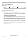
Module Base +0x___1
76543210
R000
MODFEN BIDIROE
0
SPISWAI SPC0
W
Reset 00000000
= Unimplemented or Reserved
Figure 16-4. SPI Control Register 2 (SPICR2)
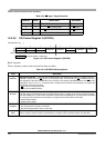
Table 16-4. SPICR2 Field Descriptions
Field Description
4
MODFEN
Mode Fault Enable Bit — This bit allows the MODF failure to be detected. If the SPI is in master mode and
MODFEN is cleared, then the
SS port pin is not used by the SPI. In slave mode, the SS is available only as an
input regardless of the value of MODFEN. For an overview on the impact of the MODFEN bit on the
SS port pin
configuration, refer to Table 16-5. In master mode, a change of this bit will abort a transmission in progress and
force the SPI system into idle state.
0
SS port pin is not used by the SPI.
1
SS port pin with MODF feature.
3
BIDIROE
Output Enable in the Bidirectional Mode of Operation — This bit controls the MOSI and MISO output buffer
of the SPI, when in bidirectional mode of operation (SPC0 is set). In master mode, this bit controls the output
buffer of the MOSI port, in slave mode it controls the output buffer of the MISO port. In master mode, with SPC0
set, a change of this bit will abort a transmission in progress and force the SPI into idle state.
0 Output buffer disabled.
1 Output buffer enabled.
1
SPISWAI
SPI Stop in Wait Mode Bit — This bit is used for power conservation while in wait mode.
0 SPI clock operates normally in wait mode.
1 Stop SPI clock generation when in wait mode.
0
SPC0
Serial Pin Control Bit 0 — This bit enables bidirectional pin configurations as shown in Table 16-5. In master
mode, a change of this bit will abort a transmission in progress and force the SPI system into idle state.