


Chapter 11 Enhanced Capture Timer (S12MC9S12XDP51216B8CV2)
MC9S12XDP512 Data Sheet, Rev. 2.11
Freescale Semiconductor 531
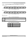
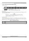
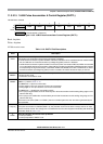
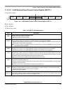
11.3.2.15 16-Bit Pulse Accumulator A Control Register (PACTL)
Read: Anytime
Write: Anytime
All bits reset to zero.
Module Base + 0x0020
76543210
R0
PAEN PAMOD PEDGE CLK1 CLK0 PAOVI PAI
W
Reset 00000000
= Unimplemented or Reserved
Figure 11-35. 16-Bit Pulse Accumulator Control Register (PACTL)
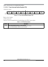
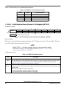
Table 11-18. PACTL Field Descriptions
Field Description
6
PAEN
Pulse Accumulator A System Enable — PAEN is independent from TEN. With timer disabled, the pulse
accumulator can still function unless pulse accumulator is disabled.
0 16-Bit Pulse Accumulator A system disabled. 8-bit PAC3 and PAC2 can be enabled when their related enable
bits in ICPAR are set. Pulse Accumulator Input Edge Flag (PAIF) function is disabled.
1 16-Bit Pulse Accumulator A system enabled. The two 8-bit pulse accumulators PAC3 and PAC2 are cascaded
to form the PACA 16-bit pulse accumulator. When PACA in enabled, the PACN3 and PACN2 registers contents
are respectively the high and low byte of the PACA. PA3EN and PA2EN control bits in ICPAR have no effect.
Pulse Accumulator Input Edge Flag (PAIF) function is enabled. The PACA shares the input pin with IC7.
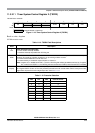
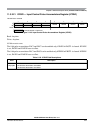
5
PAMOD
Pulse Accumulator Mode — This bit is active only when the Pulse Accumulator A is enabled (PAEN = 1).
0 Event counter mode
1 Gated time accumulation mode
4
PEDGE
Pulse Accumulator Edge Control — This bit is active only when the Pulse Accumulator A is enabled
(PAEN = 1). Refer to Table 11-19.
For PAMOD bit = 0 (event counter mode).
0 Falling edges on PT7 pin cause the count to be incremented
1 Rising edges on PT7 pin cause the count to be incremented
For PAMOD bit = 1 (gated time accumulation mode).
0 PT7 input pin high enables bus clock divided by 64 to Pulse Accumulator and the trailing falling edge on PT7
sets the PAIF flag.
1 PT7 input pin low enables bus clock divided by 64 to Pulse Accumulator and the trailing rising edge on PT7
sets the PAIF flag.
If the timer is not active (TEN = 0 in TSCR1), there is no divide-by-64 since the ÷64 clock is generated by the
timer prescaler.
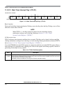
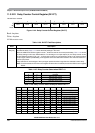
3:2
CLK[1:0]
Clock Select Bits — For the description of PACLK please refer to Figure 11-70.
If the pulse accumulator is disabled (PAEN = 0), the prescaler clock from the timer is always used as an input
clock to the timer counter. The change from one selected clock to the other happens immediately after these bits
are written. Refer to Table 11-20.
2
PAOVI
Pulse Accumulator A Overflow Interrupt Enable
0 Interrupt inhibited
1 Interrupt requested if PAOVF is set