


Chapter 20 Debug (S12XDBGV2)
MC9S12XDP512 Data Sheet, Rev. 2.11
Freescale Semiconductor 797
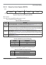
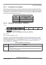
Table 20-3. DBGC1 Field Descriptions
Field Description
7
ARM
Arm Bit — The ARM bit controls whether the DBG module is armed. This bit can be set and cleared by user
software and is automatically cleared on completion of a tracing session, or if a breakpoint is generated with
tracing not enabled. On setting this bit the state sequencer enters State1. When ARM is set, the only bits in the
DBG module registers that can be written are ARM and TRIG.
0 Debugger disarmed
1 Debugger armed
6
TRIG
Immediate Trigger Request Bit — This bit when written to 1 requests an immediate trigger independent of
comparator or external tag signal status. When tracing is complete a forced breakpoint may be generated
depending upon DBGBRK and BDM bit settings. This bit always reads back a “0”. Writing a “0” to this bit has no
effect. If both TSOURCE bits are clear no tracing is carried out. If tracing has already commenced using BEGIN-
or mid-trigger alignment, it continues until the end of the tracing session as defined by the TALIGN bit settings,
thus TRIG has no affect. In secure mode tracing is disabled and writing to this bit has no effect.
0 Do not trigger until the state sequencer enters the final state.
1 Enter final state immediately and issue forced breakpoint request when trace buffer is full.
5
XGSBPE
XGATE S/W Breakpoint Enable — The XGSBPE bit controls whether an XGATE S/W breakpoint request is
passed to the CPU. The XGATE S/W breakpoint request is handled by the DBG module, which can request an
CPU breakpoint depending on the state of this bit.
0 XGATE S/W breakpoint request is disabled
1 XGATE S/W breakpoint request is enabled
4
BDM
Background Debug Mode Enable — This bit determines if a CPU breakpoint causes the system to enter
background debug mode (BDM) or initiate a software interrupt (SWI). It has no affect on DBG functionality.
This bit must be set if the BDM is enabled by the ENBDM bit in the BDM module to map breakpoints to BDM
and must be cleared if the BDM module is disabled to map breakpoints to SWI.
0 Go to software interrupt on a breakpoint
1 Go to BDM on a breakpoint.
3–2
DBGBRK
DBG Breakpoint Enable Bits — The DBGBRK bits control whether the debugger will request a breakpoint to
either CPU, XGATE or both upon reaching the state sequencer final state. If tracing is enabled, the breakpoint
is generated on completion of the tracing session. If tracing is not enabled, the breakpoint is generated
immediately. Please refer to Section 20.4.7, “Breakpoints” for further details. XGATE generated breakpoints are
independent of the DBGBRK bits. XGATE generates a forced breakpoint to the CPU only. See Table 20-4.
1–0
COMRV
Comparator Register Visibility Bits — These bits determine which bank of comparator register is visible in the
8-byte window of the DBG module address map, located between 0x0028 to 0x002F. Furthermore these bits
determine which state control register is visible at the address 0x0027. See Table 20-5.
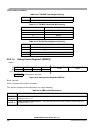
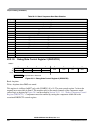
Table 20-4. DBGBRK Encoding
DBGBRK Resource Halted by Breakpoint
00 No breakpoint generated
01 XGATE breakpoint generated
10 CPU breakpoint generated
11 Breakpoints generated for CPU and XGATE
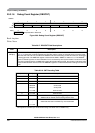
Table 20-5. COMRV Encoding
COMRV Visible Comparator Visible State Control Register
00 Comparator A DBGSCR1