


Chapter 12 Pulse-Width Modulator (S12PWM8B8CV1)
MC9S12XDP512 Data Sheet, Rev. 2.11
562 Freescale Semiconductor
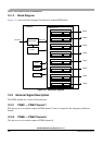
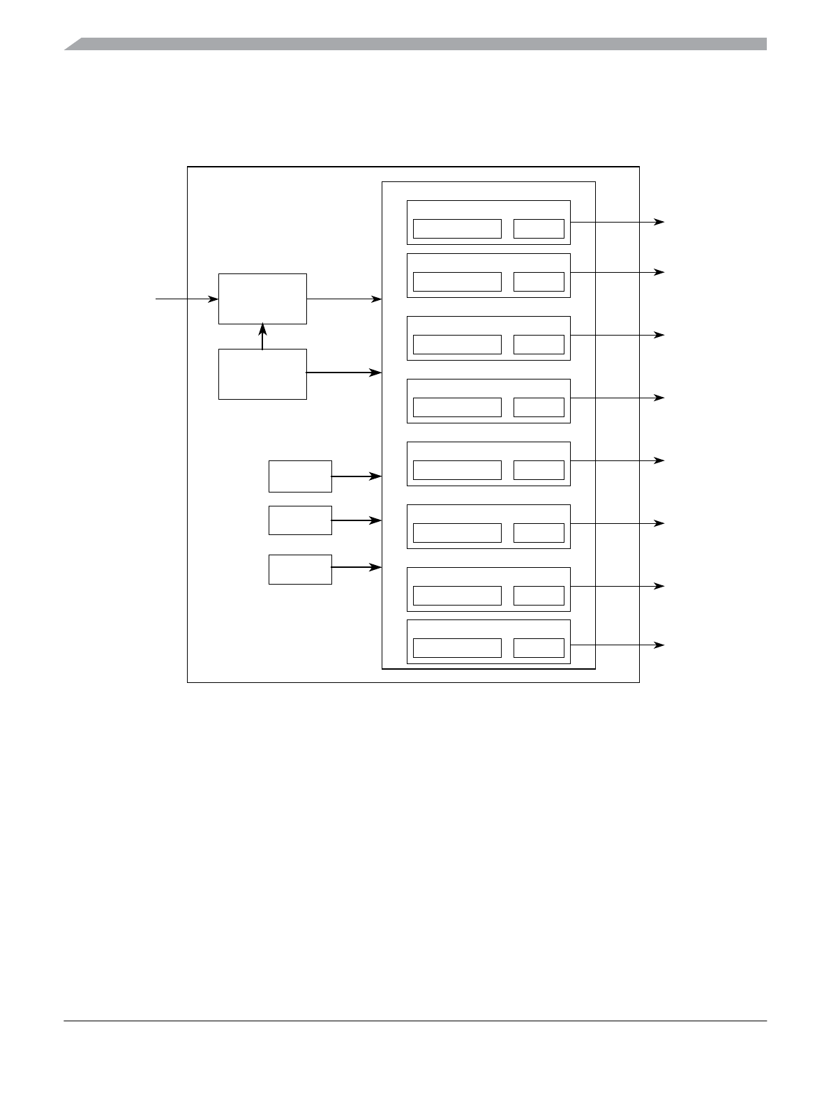
12.1.3 Block Diagram
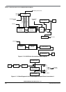
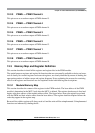
Figure 12-1 shows the block diagram for the 8-bit 8-channel PWM block.
Figure 12-1. PWM Block Diagram
12.2 External Signal Description
The PWM module has a total of 8 external pins.
12.2.1 PWM7 — PWM Channel 7
This pin serves as waveform output of PWM channel 7 and as an input for the emergency shutdown
feature.
12.2.2 PWM6 — PWM Channel 6
This pin serves as waveform output of PWM channel 6.
Period and Duty Counter
Channel 6
Clock Select
PWM Clock
Period and Duty Counter
Channel 5
Period and Duty Counter
Channel 4
Period and Duty Counter
Channel 3
Period and Duty Counter
Channel 2
Period and Duty Counter
Channel 1
Alignment
Polarity
Control
PWM8B8C
PWM6
PWM5
PWM4
PWM3
PWM2
PWM1
Enable
PWM Channels
Period and Duty Counter
Channel 7
Period and Duty Counter
Channel 0
PWM0
PWM7
Bus Clock