


Chapter 22 External Bus Interface (S12XEBIV2)
MC9S12XDP512 Data Sheet, Rev. 2.11
Freescale Semiconductor 865
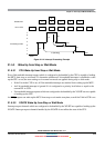
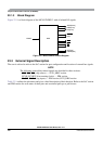
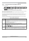
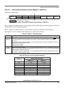
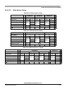
22.3.2.1 External Bus Interface Control Register 0 (EBICTL0)
Read: Anytime. In emulation modes, read operations will return the data from the external bus, in all other
modes, the data are read from this register.
Write: Anytime. In emulation modes, write operations will also be directed to the external bus.
This register controls input pin threshold level and determines the external address and data bus sizes in
normal expanded mode. If not in use with the external bus interface, the related pins can be used for
alternative functions.
External bus is available as programmed in normal expanded mode and always full-sized in emulation
modes and special test mode; function not available in single-chip modes.
Module Base +0x000E (PRR)
76543210
R
ITHRS
0
HDBE ASIZ4 ASIZ3 ASIZ2 ASIZ1 ASIZ0
W
Reset 00111111
= Unimplemented or Reserved
Figure 22-3. External Bus Interface Control Register 0 (EBICTL0)
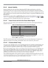
Table 22-2. EBICTL0 Field Descriptions
Field Description
7
ITHRS
Reduced Input Threshold — This bit selects reduced input threshold on external data bus pins and specific
control input signals which are in use with the external bus interface in order to adapt to external devices with a
3.3 V, 5 V tolerant I/O.
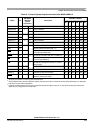
The reduced input threshold level takes effect depending on ITHRS, the operating mode and the related enable
signals of the EBI pin function as summarized in Table 22-3.
0 Input threshold is at standard level on all pins
1 Reduced input threshold level enabled on pins in use with the external bus interface
5
HDBE
High Data Byte Enable — This bit enables the higher half of the 16-bit data bus. If disabled, only the lower 8-bit
data bus can be used with the external bus interface. In this case the unused data pins and the data select
signals (
UDS and LDS) are free to be used for alternative functions.
0 DATA[15:8],
UDS, and LDS disabled
1 DATA[15:8],
UDS, and LDS enabled
4–0
ASIZ[4:0]
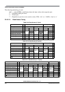
External Address Bus Size — These bits allow scalability of the external address bus. The programmed value
corresponds to the number of available low-aligned address lines (refer to Table 22-4). All address lines
ADDR[22:0] start up as outputs after reset in expanded modes. This needs to be taken into consideration when
using alternative functions on relevant pins in applications which utilize a reduced external address bus.