


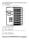

Chapter 12 Pulse-Width Modulator (S12PWM8B8CV1)
MC9S12XDP512 Data Sheet, Rev. 2.11
Freescale Semiconductor 567
An exception to this is when channels are concatenated. Once concatenated mode is enabled (CONxx bits
set in PWMCTL register), enabling/disabling the corresponding 16-bit PWM channel is controlled by the
low order PWMEx bit.In this case, the high order bytes PWMEx bits have no effect and their
corresponding PWM output lines are disabled.
While in run mode, if all eight PWM channels are disabled (PWME7–0 = 0), the prescaler counter shuts
off for power savings.
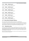
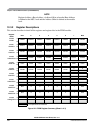
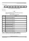
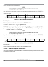
Read: Anytime
Write: Anytime
Module Base + 0x0000
76543210
R
PWME7 PWME6 PWME5 PWME4 PWME3 PWME2 PWME1 PWME0
W
Reset 00000000
Figure 12-3. PWM Enable Register (PWME)
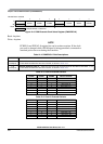
Table 12-1. PWME Field Descriptions
Field Description
7
PWME7
Pulse Width Channel 7 Enable
0 Pulse width channel 7 is disabled.
1 Pulse width channel 7 is enabled. The pulse modulated signal becomes available at PWM output bit 7 when
its clock source begins its next cycle.
6
PWME6
Pulse Width Channel 6 Enable
0 Pulse width channel 6 is disabled.
1 Pulse width channel 6 is enabled. The pulse modulated signal becomes available at PWM output bit6 when
its clock source begins its next cycle. If CON67=1, then bit has no effect and PWM output line 6 is disabled.
5
PWME5
Pulse Width Channel 5 Enable
0 Pulse width channel 5 is disabled.
1 Pulse width channel 5 is enabled. The pulse modulated signal becomes available at PWM output bit 5 when
its clock source begins its next cycle.
4
PWME4
Pulse Width Channel 4 Enable
0 Pulse width channel 4 is disabled.
1 Pulse width channel 4 is enabled. The pulse modulated signal becomes available at PWM, output bit 4 when
its clock source begins its next cycle. If CON45 = 1, then bit has no effect and PWM output bit4 is disabled.
3
PWME3
Pulse Width Channel 3 Enable
0 Pulse width channel 3 is disabled.
1 Pulse width channel 3 is enabled. The pulse modulated signal becomes available at PWM, output bit 3 when
its clock source begins its next cycle.
2
PWME2
Pulse Width Channel 2 Enable
0 Pulse width channel 2 is disabled.
1 Pulse width channel 2 is enabled. The pulse modulated signal becomes available at PWM, output bit 2 when
its clock source begins its next cycle. If CON23 = 1, then bit has no effect and PWM output bit2 is disabled.