


Chapter 12 Pulse-Width Modulator (S12PWM8B8CV1)
MC9S12XDP512 Data Sheet, Rev. 2.11
Freescale Semiconductor 575
Read: Always read $00 in normal modes
Write: Unimplemented in normal modes
NOTE
Writing to these registers when in special modes can alter the PWM
functionality.
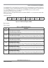
12.3.2.12 PWM Channel Counter Registers (PWMCNTx)
Each channel has a dedicated 8-bit up/down counter which runs at the rate of the selected clock source.
The counter can be read at any time without affecting the count or the operation of the PWM channel. In
left aligned output mode, the counter counts from 0 to the value in the period register - 1. In center aligned
output mode, the counter counts from 0 up to the value in the period register and then back down to 0.
Any value written to the counter causes the counter to reset to $00, the counter direction to be set to up,
the immediate load of both duty and period registers with values from the buffers, and the output to change
according to the polarity bit. The counter is also cleared at the end of the effective period (see
Section 12.4.2.5, “Left Aligned Outputs” and Section 12.4.2.6, “Center Aligned Outputs” for more
details). When the channel is disabled (PWMEx = 0), the PWMCNTx register does not count. When a
channel becomes enabled (PWMEx = 1), the associated PWM counter starts at the count in the
PWMCNTx register. For more detailed information on the operation of the counters, see Section 12.4.2.4,
“PWM Timer Counters”.
In concatenated mode, writes to the 16-bit counter by using a 16-bit access or writes to either the low or
high order byte of the counter will reset the 16-bit counter. Reads of the 16-bit counter must be made by
16-bit access to maintain data coherency.
NOTE
Writing to the counter while the channel is enabled can cause an irregular PWM cycle to occur.
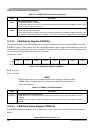
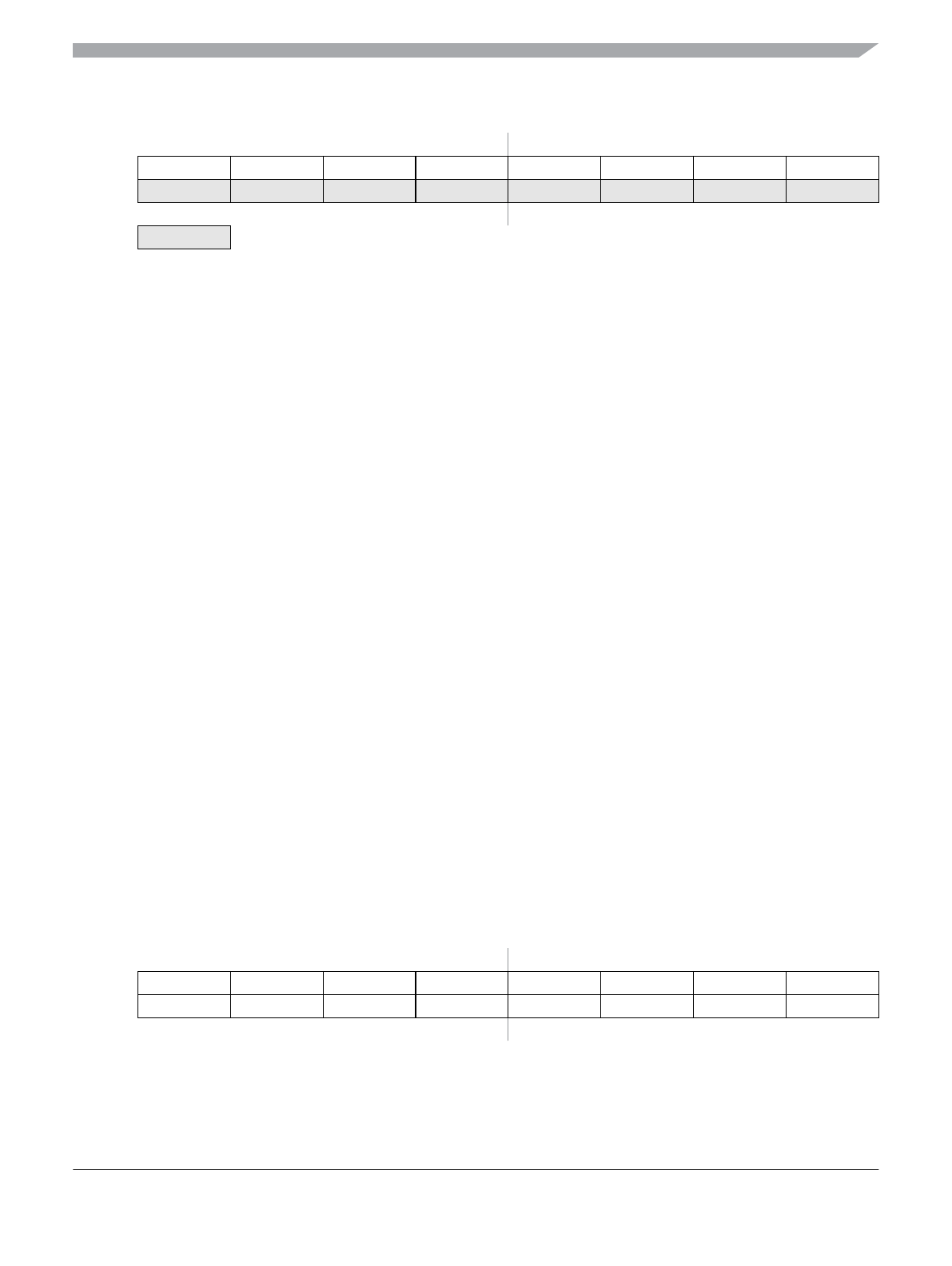
Read: Anytime
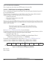
Module Base + 0x000A, 0x000B
76543210
R00000000
W
Reset 00000000
= Unimplemented or Reserved
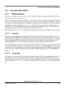
Figure 12-13. Reserved Registers (PWMSCNTx)
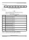
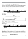
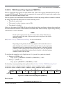
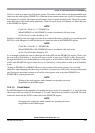
Module Base + 0x000C = PWMCNT0, 0x000D = PWMCNT1, 0x000E = PWMCNT2, 0x000F = PWMCNT3
Module Base + 0x0010 = PWMCNT4, 0x0011 = PWMCNT5, 0x0012 = PWMCNT6, 0x0013 = PWMCNT7
76543210
R Bit 7 6 5 4 3 2 1 Bit 0
W00000000
Reset 00000000
Figure 12-14. PWM Channel Counter Registers (PWMCNTx)