


Chapter 13 Inter-Integrated Circuit (MC9S12XDP512) Block Description
MC9S12XDP512 Data Sheet, Rev. 2.11
Freescale Semiconductor 605
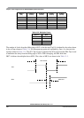
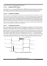
Wait mode is entered via execution of a CPU WAI instruction. In the event that the IBSWAI bit is set, all
clocks internal to the IIC will be stopped and any transmission currently in progress will halt.If the CPU
were woken up by a source other than the IIC module, then clocks would restart and the IIC would resume
from where was during the previous transmission. It is not possible for the IIC to wake up the CPU when
its internal clocks are stopped.
If it were the case that the IBSWAI bit was cleared when the WAI instruction was executed, the IIC internal
clocks and interface would remain alive, continuing the operation which was currently underway. It is also
possible to configure the IIC such that it will wake up the CPU via an interrupt at the conclusion of the
current operation. See the discussion on the IBIF and IBIE bits in the IBSR and IBCR, respectively.
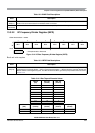
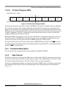
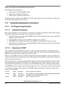
13.3.2.4 IIC Status Register (IBSR)
This status register is read-only with exception of bit 1 (IBIF) and bit 4 (IBAL), which are software
clearable.
2
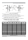
RSTA
Repeat Start — Writing a 1 to this bit will generate a repeated START condition on the bus, provided it is the
current bus master. This bit will always be read as a low. Attempting a repeated start at the wrong time, if the bus
is owned by another master, will result in loss of arbitration.
1 Generate repeat start cycle
1
RESERVED
Reserved — Bit 1 of the IBCR is reserved for future compatibility. This bit will always read 0.
0
IBSWAI
I Bus Interface Stop in Wait Mode
0 IIC bus module clock operates normally
1 Halt IIC bus module clock generation in wait mode
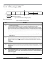
Offset Module Base + 0x0003
76543210
R TCF IAAS IBB
IBAL
0SRW
IBIF
RXAK
W
Reset 10000000
= Unimplemented or Reserved
Figure 13-7. IIC Bus Status Register (IBSR)
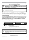
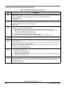
Table 13-8. IBSR Field Descriptions
Field Description
7
TCF
Data Transferring Bit — While one byte of data is being transferred, this bit is cleared. It is set by the falling
edge of the 9th clock of a byte transfer. Note that this bit is only valid during or immediately following a transfer
to the IIC module or from the IIC module.
0 Transfer in progress
1 Transfer complete
Table 13-7. IBCR Field Descriptions (continued)
Field Description