


Chapter 18 Periodic Interrupt Timer (S12PIT24B4CV1)
MC9S12XDP512 Data Sheet, Rev. 2.11
762 Freescale Semiconductor
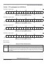
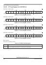
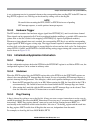
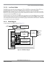
Whenever a 16-bit timer counter and the connected 8-bit micro timer counter have counted to zero, the
PITLD register is reloaded and the corresponding time-out flag PTF in the PIT time-out flag (PITTF)
register is set, as shown in Figure 18-20. The time-out period is a function of the timer load (PITLD) and
micro timer load (PITMTLD) registers and the bus clock f
BUS
:
time-out period = (PITMTLD + 1) * (PITLD + 1) / f
BUS
.
For example, for a 40 MHz bus clock, the maximum time-out period equals:
256 * 65536 * 25 ns = 419.43 ms.
The current 16-bit modulus down-counter value can be read via the PITCNT register. The micro timer
down-counter values cannot be read.
The 8-bit micro timers can individually be restarted by writing a one to the corresponding force load micro
timer PFLMT bits in the PIT control and force load micro timer (PITCFLMT) register. The 16-bit timers
can individually be restarted by writing a one to the corresponding force load timer PFLT bits in the PIT
forceload timer (PITFLT) register. If desired, any group of timers and micro timers can be restarted at the
same time by using one 16-bit write to the adjacent PITCFLMT and PITFLT registers with the relevant
bits set, as shown in Figure 18-20.
Figure 18-20. PIT Trigger and Flag Signal Timing
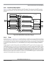
18.4.2 Interrupt Interface
Each time-out event can be used to trigger an interrupt service request. For each timer channel, an
individual bit PINTE in the PIT interrupt enable (PITINTE) register exists to enable this feature. If PINTE
Bus Clock
02
1
0
8-Bit Micro
2
1
0
2
1
0
2
1
2
1
0
PITCNT Register
0001 000000
0001 0000
8-Bit Force Load
2
1
0
2
1
0
PTF Flag
1
PITTRIG
16-Bit Force Load
0001 0000 0001
2
Time-Out Period
Time-Out Period
After Restart
Timer Counter
Note 1. The PTF flag clearing depends on the software