


Chapter 11 Enhanced Capture Timer (S12MC9S12XDP51216B8CV2)
MC9S12XDP512 Data Sheet, Rev. 2.11
536 Freescale Semiconductor
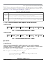
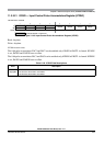
11.3.2.20 16-Bit Modulus Down-Counter FLAG Register (MCFLG)
Read: Anytime
Write only used in the flag clearing mechanism for bit 7. Writing a one to bit 7 clears the flag. Writing a
zero will not affect the current status of the bit.
NOTE
When TFFCA = 1, the flag cannot be cleared via the normal flag clearing
mechanism (writing a one to the flag). Reference Section 11.3.2.6, “Timer
System Control Register 1 (TSCR1)”.
All bits reset to zero.
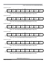
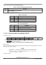
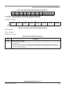
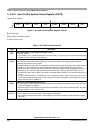
Table 11-23. Modulus Counter Prescaler Select
MCPR1 MCPR0 Prescaler Division
00 1
01 4
10 8
11 16
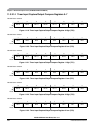
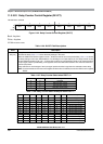
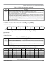
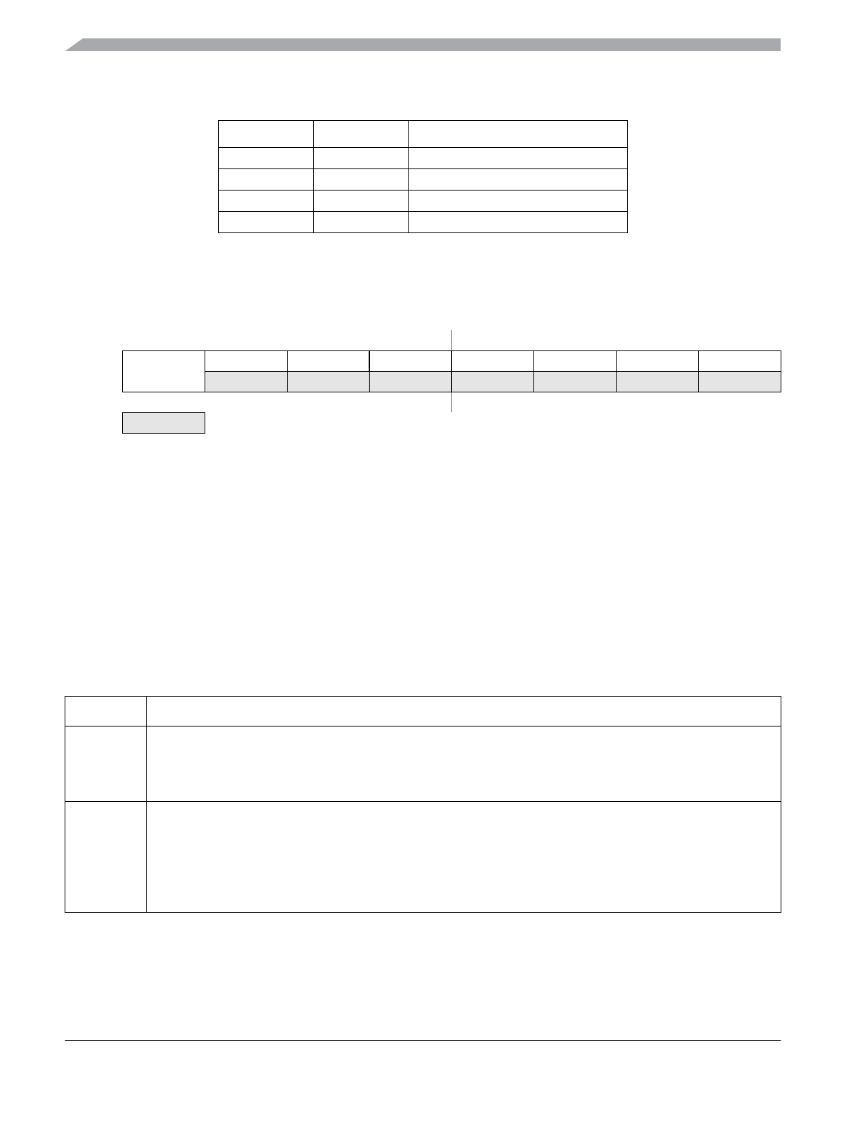
Module Base + 0x0027
76543210
R
MCZF
0 0 0 POLF3 POLF2 POLF1 POLF0
W
Reset 00000000
= Unimplemented or Reserved
Figure 11-42. 16-Bit Modulus Down-Counter FLAG Register (MCFLG)
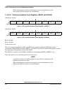
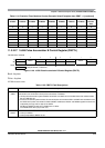
Table 11-24. MCFLG Field Descriptions
Field Description
7
MCZF
Modulus Counter Underflow Flag — The flag is set when the modulus down-counter reaches 0x0000.
The flag indicates when interrupt conditions have occurred. The flag can be cleared via the normal flag clearing
mechanism (writing a one to the flag) or via the fast flag clearing mechanism (Reference TFFCA bit in
Section 11.3.2.6, “Timer System Control Register 1 (TSCR1)”).
3:0
POLF[3:0]
First Input Capture Polarity Status — These are read only bits. Writes to these bits have no effect.
Each status bit gives the polarity of the first edge which has caused an input capture to occur after capture latch
has been read.
Each POLFx corresponds to a timer PORTx input.
0 The first input capture has been caused by a falling edge.
1 The first input capture has been caused by a rising edge.