


Chapter 12 Pulse-Width Modulator (S12PWM8B8CV1)
MC9S12XDP512 Data Sheet, Rev. 2.11
Freescale Semiconductor 571
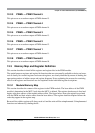
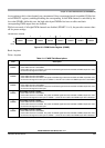
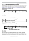
12.3.2.5 PWM Center Align Enable Register (PWMCAE)
The PWMCAE register contains eight control bits for the selection of center aligned outputs or left aligned
outputs for each PWM channel. If the CAEx bit is set to a one, the corresponding PWM output will be
center aligned. If the CAEx bit is cleared, the corresponding PWM output will be left aligned. See
Section 12.4.2.5, “Left Aligned Outputs” and Section 12.4.2.6, “Center Aligned Outputs” for a more
detailed description of the PWM output modes.
Read: Anytime
Write: Anytime
NOTE
Write these bits only when the corresponding channel is disabled.
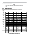
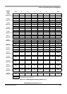
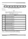
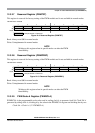
12.3.2.6 PWM Control Register (PWMCTL)
The PWMCTL register provides for various control of the PWM module.
Read: Anytime
Write: Anytime
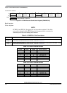
There are three control bits for concatenation, each of which is used to concatenate a pair of PWM
channels into one 16-bit channel. When channels 6 and 7are concatenated, channel 6 registers become the
high order bytes of the double byte channel. When channels 4 and 5 are concatenated, channel 4 registers
become the high order bytes of the double byte channel. When channels 2 and 3 are concatenated, channel
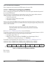
Module Base + 0x0004
76543210
R
CAE7 CAE6 CAE5 CAE4 CAE3 CAE2 CAE1 CAE0
W
Reset 00000000
Figure 12-7. PWM Center Align Enable Register (PWMCAE)
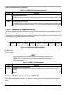
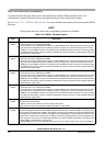
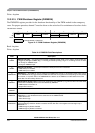
Table 12-7. PWMCAE Field Descriptions
Field Description
7–0
CAE[7:0]
Center Aligned Output Modes on Channels 7–0
0 Channels 7–0 operate in left aligned output mode.
1 Channels 7–0 operate in center aligned output mode.
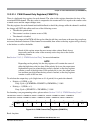
Module Base + 0x0005
76543210
R
CON67 CON45 CON23 CON01 PSWAI PFRZ
00
W
Reset 00000000
= Unimplemented or Reserved
Figure 12-8. PWM Control Register (PWMCTL)