


Chapter 15 Serial Communication Interface (S12MC9S12XDP512V5)
MC9S12XDP512 Data Sheet, Rev. 2.11
686 Freescale Semiconductor
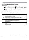
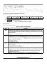
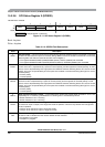
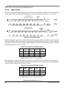
15.3.2.8 SCI Status Register 2 (SCISR2)
Read: Anytime
Write: Anytime
Module Base + 0x0005
76543210
R
AMAP
00
TXPOL RXPOL BRK13 TXDIR
RAF
W
Reset 00000000
= Unimplemented or Reserved
Figure 15-11. SCI Status Register 2 (SCISR2)
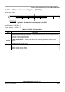
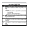
Table 15-12. SCISR2 Field Descriptions
Field Description
7
AMAP
Alternative Map — This bit controls which registers sharing the same address space are accessible. In the reset
condition the SCI behaves as previous versions. Setting AMAP=1 allows the access to another set of control and
status registers and hides the baud rate and SCI control Register 1.
0 The registers labelled SCIBDH (0x000),SCIBDL (0x001), SCICR1 (0x0002) are accessible
1 The registers labelled SCIASR1 (0x000a),SCIACR1 (0x001a), SCIACR2 (0x0002a) are accessible
4
TXPOL
Transmit Polarity — This bit control the polarity of the transmitted data. In NRZ format, a one is represented by
a mark and a zero is represented by a space for normal polarity, and the opposite for inverted polarity. In IrDA
format, a zero is represented by short high pulse in the middle of a bit time remaining idle low for a one for normal
polarity, and a zero is represented by short low pulse in the middle of a bit time remaining idle high for a one for
inverted polarity.
0 Normal polarity
1 Inverted polarity
3
RXPOL
Receive Polarity — This bit control the polarity of the received data. In NRZ format, a one is represented by a
mark and a zero is represented by a space for normal polarity, and the opposite for inverted polarity. In IrDA
format, a zero is represented by short high pulse in the middle of a bit time remaining idle low for a one for normal
polarity, and a zero is represented by short low pulse in the middle of a bit time remaining idle high for a one for
inverted polarity.
0 Normal polarity
1 Inverted polarity
2
BRK13
Break Transmit Character Length — This bit determines whether the transmit break character is 10 or 11 bit
respectively 13 or 14 bits long. The detection of a framing error is not affected by this bit.
0 Break character is 10 or 11 bit long
1 Break character is 13 or 14 bit long
1
TXDIR
Transmitter Pin Data Direction in Single-Wire Mode — This bit determines whether the TXD pin is going to
be used as an input or output, in the single-wire mode of operation. This bit is only relevant in the single-wire
mode of operation.
0 TXD pin to be used as an input in single-wire mode
1 TXD pin to be used as an output in single-wire mode
0
RAF
Receiver Active Flag — RAF is set when the receiver detects a logic 0 during the RT1 time period of the start
bit search. RAF is cleared when the receiver detects an idle character.
0 No reception in progress
1 Reception in progress