


Chapter 15 Serial Communication Interface (S12MC9S12XDP512V5)
MC9S12XDP512 Data Sheet, Rev. 2.11
696 Freescale Semiconductor
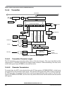
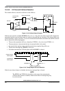
15.4.5.5 LIN Transmit Collision Detection
This module allows to check for collisions on the LIN bus.
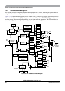
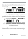
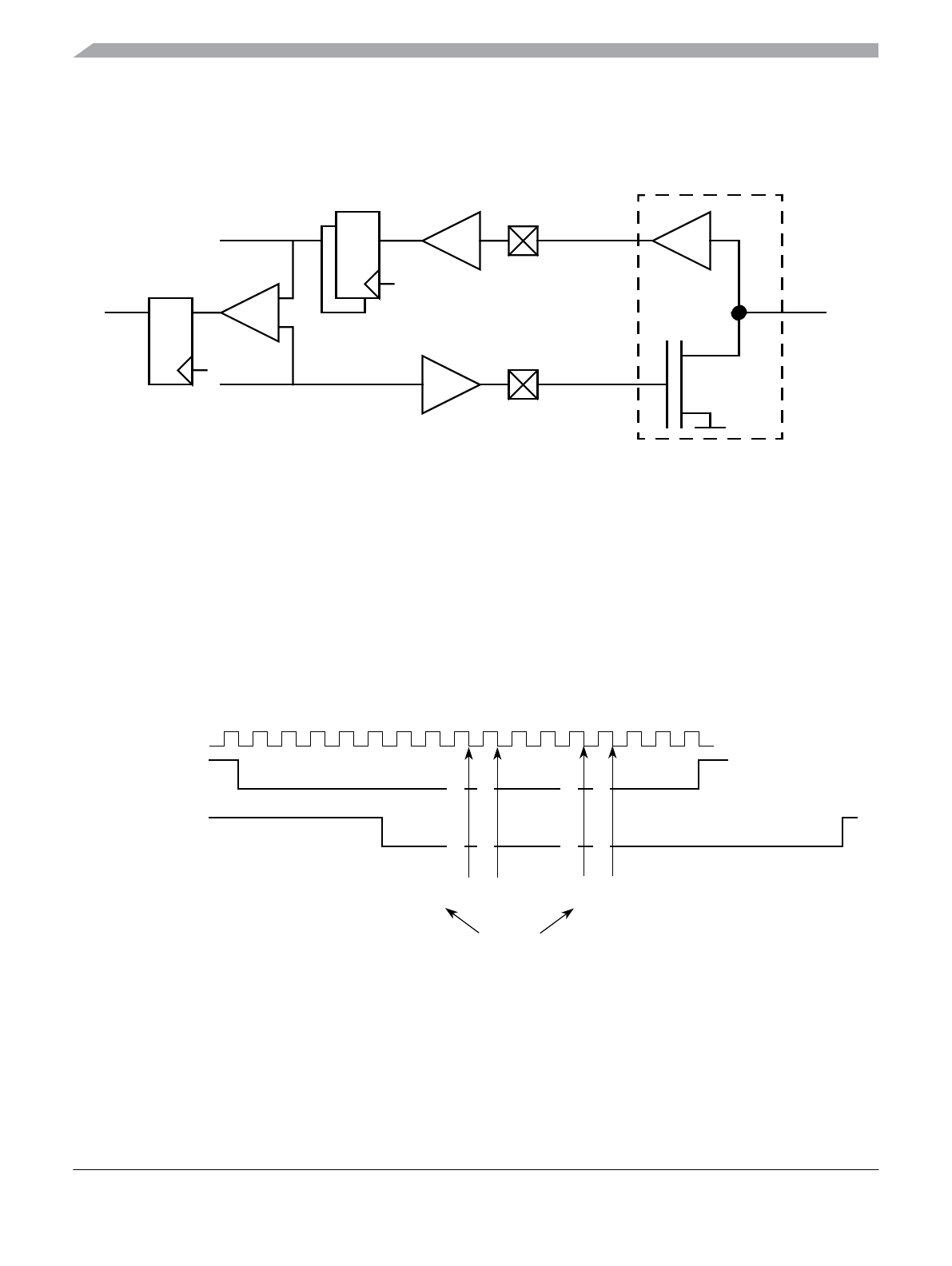
Figure 15-18. Collision Detect Principle
If the bit error circuit is enabled (BERRM[1:0] = 0:1 or = 1:0]), the error detect circuit will compare the
transmitted and the received data stream at a point in time and flag any mismatch. The timing checks run
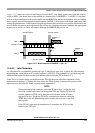
when transmitter is active (not idle). As soon as a mismatch between the transmitted data and the received
data is detected the following happens:
• The next bit transmitted will have a high level (TXPOL = 0) or low level (TXPOL = 1)
• The transmission is aborted and the byte in transmit buffer is discarded.
• the transmit data register empty and the transmission complete flag will be set
• The bit error interrupt flag, BERRIF, will be set.
• No further transmissions will take place until the BERRIF is cleared.
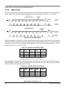
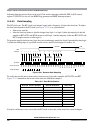
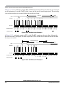
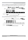
Figure 15-19. Timing Diagram Bit Error Detection
If the bit error detect feature is disabled, the bit error interrupt flag is cleared.
NOTE
The RXPOL and TXPOL bit should be set the same when transmission
collision detect feature is enabled, otherwise the bit error interrupt flag may
be set incorrectly.
TXD Pin
RXD Pin
LIN Physical Interface
Synchronizer Stage
Bus Clock
Receive Shift
Register
Transmit Shift
Register
LIN Bus
Compare
Sample
Bit Error
Point
Output Transmit
Shift Register
01234567891011121314150
Input Receive
Shift Register
BERRM[1:0] = 0:1 BERRM[1:0] = 1:1
Compare Sample Points
Sampling Begin
Sampling Begin
Sampling End
Sampling End