


Chapter 15 Serial Communication Interface (S12MC9S12XDP512V5)
MC9S12XDP512 Data Sheet, Rev. 2.11
702 Freescale Semiconductor
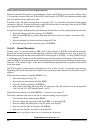
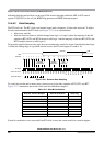
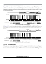
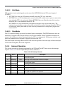
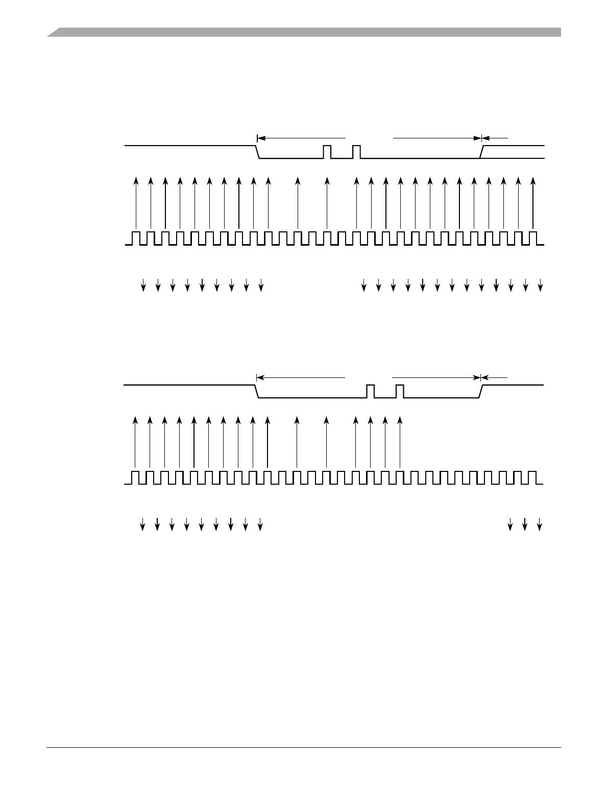
Figure 15-26 shows a burst of noise near the beginning of the start bit that resets the RT clock. The sample
after the reset is low but is not preceded by three high samples that would qualify as a falling edge.
Depending on the timing of the start bit search and on the data, the frame may be missed entirely or it may
set the framing error flag.
Figure 15-26. Start Bit Search Example 5
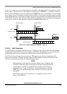
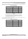
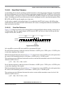
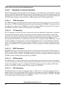
In Figure 15-27, a noise burst makes the majority of data samples RT8, RT9, and RT10 high. This sets the
noise flag but does not reset the RT clock. In start bits only, the RT8, RT9, and RT10 data samples are
ignored.
Figure 15-27. Start Bit Search Example 6
15.4.6.4 Framing Errors
If the data recovery logic does not detect a logic 1 where the stop bit should be in an incoming frame, it
sets the framing error flag, FE, in SCI status register 1 (SCISR1). A break character also sets the FE flag
because a break character has no stop bit. The FE flag is set at the same time that the RDRF flag is set.
Reset RT Clock
RT1
RT1
RT1
RT1
RT1
RT1
RT1
RT1
RT1
RT1
RT2
RT3
RT4
RT7
RT6
RT5
RT1
RT1
RT1
RT1
RT1
RT1
RT1
RT1
RT1
RT1
RT1
RT1
Samples
RT Clock
RT Clock Count
Start Bit
RXD
11111010
LSB
11 1 1 1 0000000 0
No Start Bit Found
Reset RT Clock
RT1
RT1
RT1
RT1
RT1
RT1
RT1
RT1
RT1
RT1
RT2
RT3
RT4
RT7
RT6
RT5
RT10
RT9
RT8
RT14
RT13
RT12
RT11
RT15
RT16
RT1
RT2
RT3
Samples
RT Clock
RT Clock Count
Start Bit
RXD
11111000
LSB
11 1 1 0 110