


Chapter 12 Pulse-Width Modulator (S12PWM8B8CV1)
MC9S12XDP512 Data Sheet, Rev. 2.11
568 Freescale Semiconductor
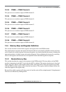
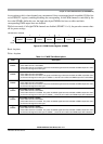
12.3.2.2 PWM Polarity Register (PWMPOL)
The starting polarity of each PWM channel waveform is determined by the associated PPOLx bit in the
PWMPOL register. If the polarity bit is one, the PWM channel output is high at the beginning of the cycle
and then goes low when the duty count is reached. Conversely, if the polarity bit is zero, the output starts
low and then goes high when the duty count is reached.
Read: Anytime
Write: Anytime
NOTE
PPOLx register bits can be written anytime. If the polarity is changed while
a PWM signal is being generated, a truncated or stretched pulse can occur
during the transition
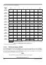
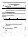
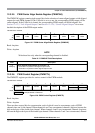
12.3.2.3 PWM Clock Select Register (PWMCLK)
Each PWM channel has a choice of two clocks to use as the clock source for that channel as described
below.
1
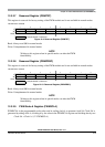
PWME1
Pulse Width Channel 1 Enable
0 Pulse width channel 1 is disabled.
1 Pulse width channel 1 is enabled. The pulse modulated signal becomes available at PWM, output bit 1 when
its clock source begins its next cycle.
0
PWME0
Pulse Width Channel 0 Enable
0 Pulse width channel 0 is disabled.
1 Pulse width channel 0 is enabled. The pulse modulated signal becomes available at PWM, output bit 0 when
its clock source begins its next cycle. If CON01 = 1, then bit has no effect and PWM output line0 is disabled.
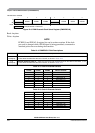
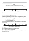
Module Base + 0x0001
76543210
R
PPOL7 PPOL6 PPOL5 PPOL4 PPOL3 PPOL2 PPOL1 PPOL0
W
Reset 00000000
Figure 12-4. PWM Polarity Register (PWMPOL)
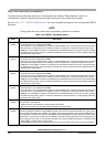
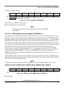
Table 12-2. PWMPOL Field Descriptions
Field Description
7–0
PPOL[7:0]
Pulse Width Channel 7–0 Polarity Bits
0 PWM channel 7–0 outputs are low at the beginning of the period, then go high when the duty count is
reached.
1 PWM channel 7–0 outputs are high at the beginning of the period, then go low when the duty count is
reached.
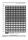
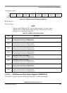
Table 12-1. PWME Field Descriptions (continued)
Field Description