


Chapter 14 Freescale’s Scalable Controller Area Network (S12MSCANV3)
MC9S12XDP512 Data Sheet, Rev. 2.11
Freescale Semiconductor 649
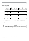
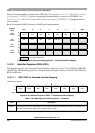
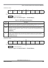
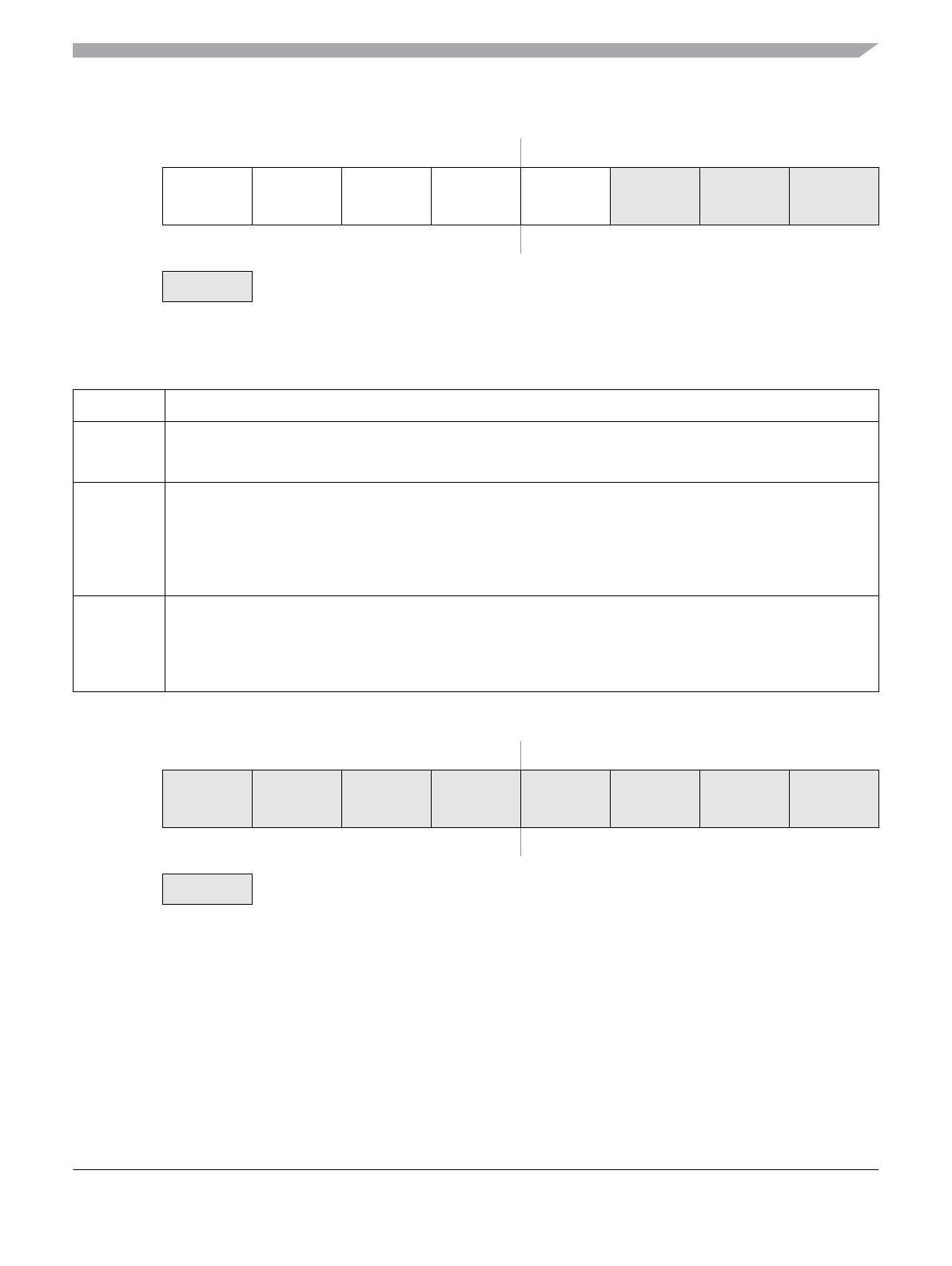
Module Base + 0x00X1
76543210
R
ID2 ID1 ID0 RTR IDE (=0)
W
Reset: xxxxxxxx
= Unused; always read ‘x’
Figure 14-30. Identifier Register 1 — Standard Mapping
Table 14-31. IDR1 Register Field Descriptions
Field Description
7:5
ID[2:0]
Standard Format Identifier — The identifiers consist of 11 bits (ID[10:0]) for the standard format. ID10 is the
most significant bit and is transmitted first on the CAN bus during the arbitration procedure. The priority of an
identifier is defined to be highest for the smallest binary number. See also ID bits in Table 14-30.
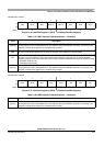
4
RTR
Remote Transmission Request — This flag reflects the status of the Remote Transmission Request bit in the
CAN frame. In the case of a receive buffer, it indicates the status of the received frame and supports the
transmission of an answering frame in software. In the case of a transmit buffer, this flag defines the setting of
the RTR bit to be sent.
0 Data frame
1 Remote frame
3
IDE
ID Extended — This flag indicates whether the extended or standard identifier format is applied in this buffer. In
the case of a receive buffer, the flag is set as received and indicates to the CPU how to process the buffer
identifier registers. In the case of a transmit buffer, the flag indicates to the MSCAN what type of identifier to send.
0 Standard format (11 bit)
1 Extended format (29 bit)
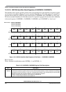
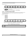
Module Base + 0x00X2
76543210
R
W
Reset: xxxxxxxx
= Unused; always read ‘x’
Figure 14-31. Identifier Register 2 — Standard Mapping