


MC9S12XDP512 Data Sheet, Rev. 2.11
Freescale Semiconductor 749
Chapter 18
Periodic Interrupt Timer (S12PIT24B4CV1)
18.1 Introduction
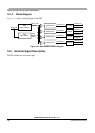
The period interrupt timer (PIT) is an array of 24-bit timers that can be used to trigger peripheral modules
or raise periodic interrupts. Refer to Figure 18-1 for a simplified block diagram.
18.1.1 Features
The MC9S12XDP512 includes these features:
• Four timers implemented as modulus down-counters with independent time-out periods.
• Time-out periods selectable between 1 and 2
24
bus clock cycles. Time-out equals m*n bus clock
cycles with 1 <= m <= 256 and 1 <= n <= 65536.
• Timers that can be enabled individually.
• Four time-out interrupts.
• Four time-out trigger output signals available to trigger peripheral modules.
• Start of timer channels can be aligned to each other.
18.1.2 Modes of Operation
Refer to the SoC guide for a detailed explanation of the chip modes.
• Run mode
This is the basic mode of operation.
• Wait mode
PIT operation in wait mode is controlled by the PITSWAI bit located in the PITCFLMT register.
In wait mode, if the bus clock is globally enabled and if the PITSWAI bit is clear, the PIT operates
like in run mode. In wait mode, if the PITSWAI bit is set, the PIT module is stalled.
• Stop mode
In full stop mode or pseudo stop mode, the PIT module is stalled.
• Freeze mode
PIT operation in freeze mode is controlled by the PITFRZ bit located in the PITCFLMT register.
In freeze mode, if the PITFRZ bit is clear, the PIT operates like in run mode. In freeze mode, if the
PITFRZ bit is set, the PIT module is stalled.