


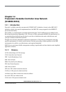

Chapter 13 Inter-Integrated Circuit (MC9S12XDP512) Block Description
MC9S12XDP512 Data Sheet, Rev. 2.11
612 Freescale Semiconductor
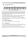
IIC Interrupt can be generated on
1. Arbitration lost condition (IBAL bit set)
2. Byte transfer condition (TCF bit set)
3. Address detect condition (IAAS bit set)
The IIC interrupt is enabled by the IBIE bit in the IIC control register. It must be cleared by writing 0 to
the IBF bit in the interrupt service routine.
13.7 Initialization/Application Information
13.7.1 IIC Programming Examples
13.7.1.1 Initialization Sequence
Reset will put the IIC bus control register to its default status. Before the interface can be used to transfer
serial data, an initialization procedure must be carried out, as follows:
1. Update the frequency divider register (IBFD) and select the required division ratio to obtain SCL
frequency from system clock.
2. Update the IIC bus address register (IBAD) to define its slave address.
3. Set the IBEN bit of the IIC bus control register (IBCR) to enable the IIC interface system.
4. Modify the bits of the IIC bus control register (IBCR) to select master/slave mode, transmit/receive
mode and interrupt enable or not.
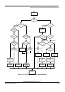
13.7.1.2 Generation of START
After completion of the initialization procedure, serial data can be transmitted by selecting the 'master
transmitter' mode. If the device is connected to a multi-master bus system, the state of the IIC bus busy bit
(IBB) must be tested to check whether the serial bus is free.
If the bus is free (IBB=0), the start condition and the first byte (the slave address) can be sent. The data
written to the data register comprises the slave calling address and the LSB set to indicate the direction of
transfer required from the slave.
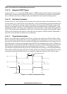
The bus free time (i.e., the time between a STOP condition and the following START condition) is built
into the hardware that generates the START cycle. Depending on the relative frequencies of the system
clock and the SCL period it may be necessary to wait until the IIC is busy after writing the calling address
to the IBDR before proceeding with the following instructions. This is illustrated in the following example.
An example of a program which generates the START signal and transmits the first byte of data (slave
address) is shown below:
CHFLAG BRSET IBSR,#$20,* ;WAIT FOR IBB FLAG TO CLEAR
TXSTART BSET IBCR,#$30 ;SET TRANSMIT AND MASTER MODE;i.e. GENERATE START CONDITION
MOVB CALLING,IBDR ;TRANSMIT THE CALLING ADDRESS, D0=R/W
IBFREE BRCLR IBSR,#$20,* ;WAIT FOR IBB FLAG TO SET