


512 Kbyte Flash Module (S12XFTX512K4V2)
BookTitle, Rev. 2.4
Freescale Semiconductor 117
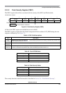
CBEIF, PVIOL, and ACCERR are readable and writable, CCIF and BLANK are readable and not writable,
remaining bits read 0 and are not writable in normal mode. FAIL is readable and writable in special mode.
FAIL must be clear in special mode when starting a command write sequence.
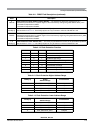
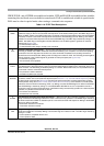
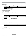
Table 2-16. FSTAT Field Descriptions
Field Description
7
CBEIF
Command Buffer Empty Interrupt Flag — The CBEIF flag indicates that the address, data and command
buffers are empty so that a new command write sequence can be started. Writing a 0 to the CBEIF flag has no
effect on CBEIF. Writing a 0 to CBEIF after writing an aligned word to the Flash address space, but before CBEIF
is cleared, will abort a command write sequence and cause the ACCERR flag to be set. Writing a 0 to CBEIF
outside of a command write sequence will not set the ACCERR flag. The CBEIF flag is cleared by writing a 1 to
CBEIF. The CBEIF flag is used together with the CBEIE bit in the FCNFG register to generate an interrupt
request (see Figure 2-32).
0 Command buffers are full.
1 Command buffers are ready to accept a new command.
6
CCIF
Command Complete Interrupt Flag — The CCIF flag indicates that there are no more commands pending. The
CCIF flag is cleared when CBEIF is cleared and sets automatically upon completion of all active and pending
commands. The CCIF flag does not set when an active commands completes and a pending command is
fetched from the command buffer. Writing to the CCIF flag has no effect on CCIF. The CCIF flag is used together
with the CCIE bit in the FCNFG register to generate an interrupt request (see Figure 2-32).
0 Command in progress.
1 All commands are completed.
5
PVIOL
Protection Violation Flag —The PVIOL flag indicates an attempt was made to program or erase an address in
a protected area of the Flash memory during a command write sequence. Writing a 0 to the PVIOL flag has no
effect on PVIOL. The PVIOL flag is cleared by writing a 1 to PVIOL. While PVIOL is set, it is not possibleto launch
a command or start a command write sequence.
0 No protection violation detected.
1 Protection violation has occurred.
4
ACCERR
Access Error Flag — The ACCERR flag indicates an illegal access has occurred to the Flash memory caused
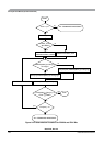
by either a violation of the command write sequence (see Section 2.4.1.2, “Command Write Sequence”), issuing
an illegal Flash command (see Table 2-18), launching the sector erase abort command terminating a sector
erase operation early (see Section 2.4.2.6, “Sector Erase Abort Command”) or the execution of a CPU STOP
instruction while a command is executing (CCIF = 0). Writing a 0 to the ACCERR flag has no effect on ACCERR.
The ACCERR flag is cleared by writing a 1 to ACCERR.While ACCERR is set, it is not possible to launch a
command or start a command write sequence. If ACCERR is set by an erase verify operation or a data compress
operation, any buffered command will not launch.
0 No access error detected.
1 Access error has occurred.
2
BLANK
Flag Indicating the Erase Verify Operation Status — When the CCIF flag is set after completion of an erase
verify command, the BLANK flag indicates the result of the erase verify operation. The BLANK flag is cleared by
the Flash module when CBEIF is cleared as part of a new valid command write sequence. Writing to the BLANK
flag has no effect on BLANK.
0 Flash block verified as not erased.
1 Flash block verified as erased.
1
FAIL
Flag Indicating a Failed Flash Operation — The FAIL flag will set if the erase verify operation fails (selected
Flash block verified as not erased). Writing a 0 to the FAIL flag has no effect on FAIL. The FAIL flag is cleared by
writing a 1 to FAIL.
0 Flash operation completed without error.
1 Flash operation failed.