


Chapter 18 Periodic Interrupt Timer (S12PIT24B4CV1)
MC9S12XDP512 Data Sheet, Rev. 2.11
Freescale Semiconductor 761
18.4 Functional Description
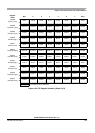
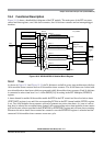
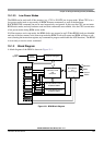
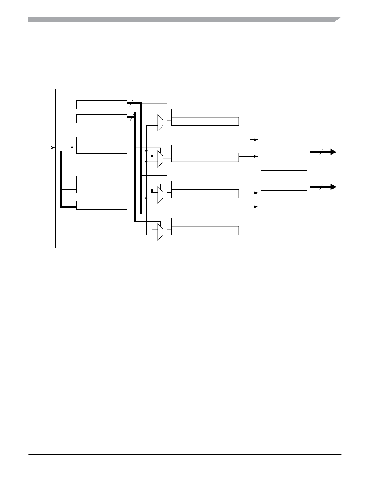
Figure 18-19 shows a detailed block diagram of the PIT module. The main parts of the PIT are status,
control and data registers, two 8-bit down-counters, four 16-bit down-counters and an interrupt/trigger
interface.
Figure 18-19. MC9S12XDP512 Detailed Block Diagram
18.4.1 Timer
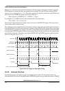
As shown in Figure 18-1and Figure 18-19, the 24-bit timers are built in a two-stage architecture with four
16-bit modulus down-counters and two 8-bit modulus down-counters. The 16-bit timers are clocked with
two selectable micro time bases which are generated with 8-bit modulus down-counters. Each 16-bit timer
is connected to micro time base 0 or 1 via the PMUX[3:0] bit setting in the PIT Multiplex (PITMUX)
register.
A timer channel is enabled if the module enable bit PITE in the PIT control and force load micro timer
(PITCFLMT) register is set and if the corresponding PCE bit in the PIT channel enable (PITCE) register
is set. Two 8-bit modulus down-counters are used to generate two micro time bases. As soon as a micro
time base is selected for an enabled timer channel, the corresponding micro timer modulus down-counter
will load its start value as specified in the PITMTLD0 or PITMTLD1 register and will start down-counting.
Whenever the micro timer down-counter has counted to zero the PITMTLD register is reloaded and the
connected 16-bit modulus down-counters count one cycle.
PITMLD0 Register
8-Bit Micro Timer 0
PITCFLMT Register
PITLD0 Register
PITMLD1 Register
8-Bit Micro Timer 1
PITMUX Register
PITFLT Register
PITCNT0 Register
Timer 0
PMUX0
PFLT0
4
4
PITTF Register
PITINTE Register
Interrupt /
Hardware
Trigger
4
Interrupt
Request
4
PITLD1 Register
PITCNT1 Register
Timer 1
[1]
PFLT1
PITLD2 Register
PITCNT2 Register
Timer 2
[2]
PFLT2
PITLD3 Register
PITCNT3 Register
Timer 3
PMUX3
PFLT3
time-out 0
time-
out 1
time-
out 2
Time-Out 3
PFLMT
[1]
[0]
PMUX
Trigger Interface
Bus
Clock
PIT_24B4C