


Chapter 5 Clocks and Reset Generator (S12CRGV6)
MC9S12XDP512 Data Sheet, Rev. 2.11
282 Freescale Semiconductor
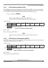
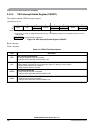
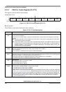
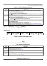
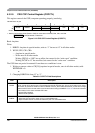
5.3.2.7 CRG PLL Control Register (PLLCTL)
This register controls the PLL functionality.
Read: Anytime
Write: Refer to each bit for individual write conditions
Module Base +0x_06
76543210
R
CME PLLON AUTO ACQ FSTWKP PRE PCE SCME
W
Reset 11110001
Figure 5-10. CRG PLL Control Register (PLLCTL)
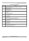
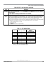
Table 5-5. PLLCTL Field Descriptions
Field Description
7
CME
Clock Monitor Enable Bit — CME enables the clock monitor. Write anytime except when SCM = 1.
0 Clock monitor is disabled.
1 Clock monitor is enabled. Slow or stopped clocks will cause a clock monitor reset sequence or self clock
mode.
Note: Operating with CME = 0 will not detect any loss of clock. In case of poor clock quality, this could cause
unpredictable operation of the MCU!
Note: In stop mode (PSTP = 0) the clock monitor is disabled independently of the CME bit setting and any loss
of external clock will not be detected. Also after wake-up from stop mode (PSTP = 0) with fast wake-up
enabled (FSTWKP = 1) the clock monitor is disabled independently of the CME bit setting and any loss
of external clock will not be detected.
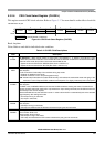
6
PLLON
Phase Lock Loop On Bit — PLLON turns on the PLL circuitry. In self clock mode, the PLL is turned on, but the
PLLON bit reads the last latched value. Write anytime except when PLLSEL = 1.
0 PLL is turned off.
1 PLL is turned on. If AUTO bit is set, the PLL will lock automatically.
5
AUTO
Automatic Bandwidth Control Bit — AUTO selects either the high bandwidth (acquisition) mode or the low
bandwidth (tracking) mode depending on how close to the desired frequency the VCO is running. Write anytime
except when PLLWAI = 1, because PLLWAI sets the AUTO bit to 1.
0 Automatic mode control is disabled and the PLL is under software control, using ACQ bit.
1 Automatic mode control is enabled and ACQ bit has no effect.
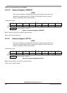
4
ACQ
Acquisition Bit
Write anytime. If AUTO=1 this bit has no effect.
0 Low bandwidth filter is selected.
1 High bandwidth filter is selected.
3
FSTWKP
Fast Wake-up from Full Stop Bit — FSTWKP enables fast wake-up from full stop mode. Write anytime. If
self-clock mode is disabled (SCME = 0) this bit has no effect.
0 Fast wake-up from full stop mode is disabled.
1 Fast wake-up from full stop mode is enabled.
When waking up from full stop mode the system will immediately resume operation in self-clock mode (see
Section 5.4.1.4, “Clock Quality Checker”). The SCMIF flag will not be set. The system will remain in self-clock
mode with oscillator and clock monitor disabled until FSTWKP bit is cleared. The clearing of FSTWKP will
start the oscillator, the clock monitor and the clock quality check. If the clock quality check is successful, the
CRG will switch all system clocks to OSCCLK. The SCMIF flag will be set. See application examples in
Figure 5-23 and Figure 5-24.