


Chapter 20 Debug (S12XDBGV2)
MC9S12XDP512 Data Sheet, Rev. 2.11
808 Freescale Semiconductor
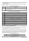
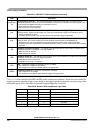
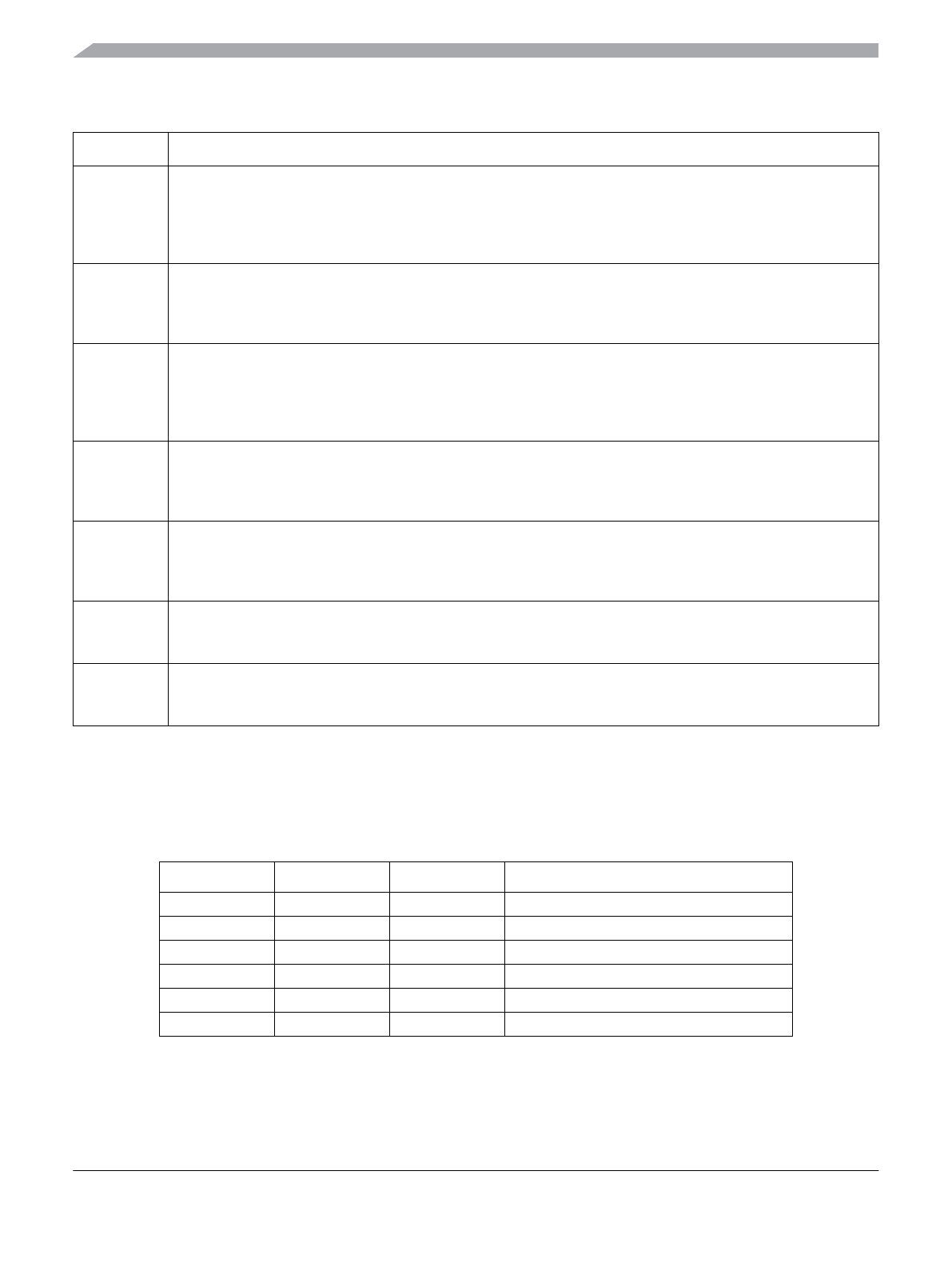
Table 20-28 shows the effect for RWE and RW on the comparison conditions. These bits are not useful for
tagged operations since the trigger occurs based on the tagged opcode reaching the execution stage of the
instruction queue. Thus, these bits are ignored if tagged triggering is selected.
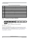
6
(COMP B/D)
SZ
Size Comparator Value Bit — The SZ bit selects either word or byte access size in comparison for the
associated comparator. This bit is ignored if the SZE bit is cleared or if the TAG bit in the same register is set.
This bit position has NDB functionality for comparators A and C
0 Word access size will be compared
1 Byte access size will be compared
5
TAG
Tag Select — This bit controls whether the comparator match will cause a trigger or tag the opcode at the
matched address. Tagged opcodes trigger only if they reach the execution stage of the instruction queue.
0 Trigger immediately on match
1 On match, tag the opcode. If the opcode is about to be executed a trigger is generated
4
BRK
Break — This bit controls whether a comparator match can cause an immediate breakpoint independent of state
sequencer state. The module breakpoints must be enabled using the DBGC1 bits DBGBRK[1:0].
0 Breakpoints may only be generated from this channel when the state machine reaches final state.
1 A match on this channel generates an immediate breakpoint, tracing, if active, is terminated and the module
disarmed.
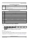
3
RW
Read/Write Comparator Value Bit — The RW bit controls whether read or write is used in compare for the
associated comparator. The RW bit is not used if RWE = 0.
0 Write cycle will be matched
1 Read cycle will be matched
2
RWE
Read/Write Enable Bit — The RWE bit controls whether read or write comparison is enabled for the associated
comparator. This bit is not useful for tagged operations.
1 Read/Write is used in comparison
0 Read/Write is not used in comparison
1
SRC
SRC — Determines mapping of comparator to CPU or XGATE
0 The comparator is mapped to CPU busses
1 The comparator is mapped to XGATE address and data busses
0
COMPE
Comparator Enable Bit— Determines if comparator is enabled
0 The comparator is not enabled
1 The comparator is enabled for state sequence triggers or tag generation
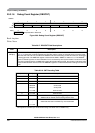
Table 20-28. Read or Write Comparison Logic Table
RWE Bit RW Bit RW Signal Comment
0 x 0 RW not used in comparison
0 x 1 RW not used in comparison
1 0 0 Write data bus
1 0 1 No match
1 1 0 No match
1 1 1 Read data bus
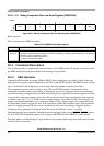
Table 20-27. DBGXCTL Field Descriptions (continued)
Field Description