


Chapter 9 XGATE (S12XGATEV2)
MC9S12XDP512 Data Sheet, Rev. 2.11
Freescale Semiconductor 393
9.4.2 Programmer’s Model
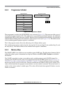
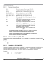
Figure 9-19. Programmer’s Model
The programmer’s model of the XGATE RISC core is shown in Figure 9-19. The processor offers a set of
seven general purpose registers (R1 - R7), which serve as accumulators and index registers. An additional
eighth register (R0) is tied to the value “$0000”. Register R1 has an additional functionality. It is preloaded
with the initial variable pointer of the channel’s service request vector (see Figure 9-20). The initial content
of the remaining general purpose registers is undefined.
The 16 bit program counter allows the addressing of a 64 kbyte address space.
The condition code register contains four bits: the sign bit (S), the zero flag (Z), the overflow flag (V), and
the carry bit (C). The initial content of the condition code register is undefined.
9.4.3 Memory Map
The XGATE’s RISC core is able to access an address space of 64K bytes. The allocation of memory blocks
within this address space is determined on chip level. Refer to the S12X_MMC Section for a detailed
information.
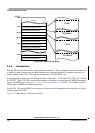
The XGATE vector block assigns a start address and a variable pointer to each XGATE channel. Its
position in the XGATE memory map can be adjusted through the XGVBR register (see Section 9.3.2.3,
“XGATE Vector Base Address Register (XGVBR)”). Figure 9-20 shows the layout of the vector block.
Each vector consists of two 16-bit words. The first contains the start address of the service routine. This
value will be loaded into the program counter before a service routine is executed. The second word is a
pointer to the service routine’s variable space. This value will be loaded into register R1 before a service
routine is executed.
R7
R6
R5
R4
R3
R2
R1
R0 = 0
VC
Register Block
Program Counter
Condition
Code
Register
15
15
15
15
15
15
15
15
0
0
0
0
0
0
0
0
1
0
(Variable Pointer)
PC
15 0
NZ
3
2