


Chapter 13 Inter-Integrated Circuit (MC9S12XDP512) Block Description
MC9S12XDP512 Data Sheet, Rev. 2.11
594 Freescale Semiconductor
13.1.2 Modes of Operation
The IIC functions the same in normal, special, and emulation modes. It has two low power modes: wait
and stop modes.
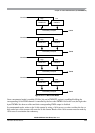
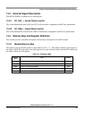
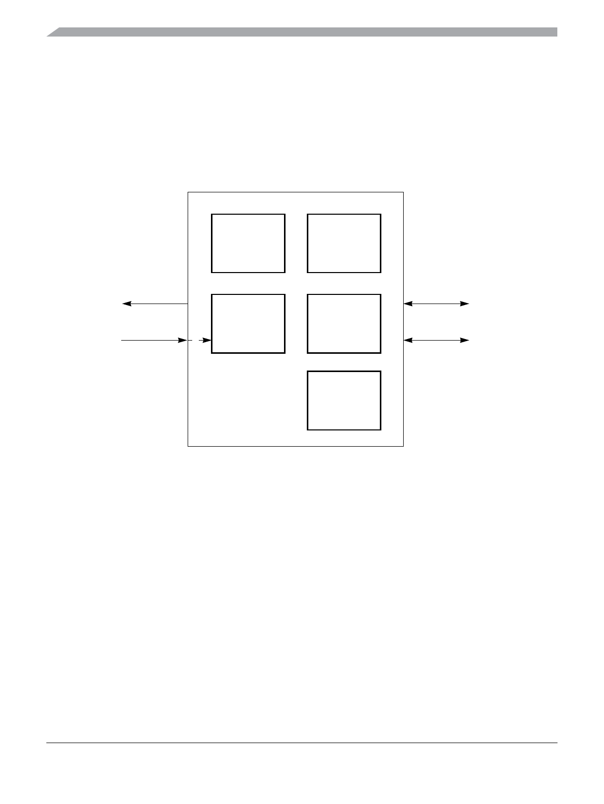
13.1.3 Block Diagram
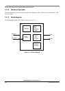
The block diagram of the IIC module is shown in Figure 13-1.
Figure 13-1. IIC Block Diagram
In/Out
Data
Shift
Register
Address
Compare
SDA
Interrupt
Clock
Control
Start
Stop
Arbitration
Control
SCL
bus_clock
IIC
Registers