


Chapter 16 Serial Peripheral Interface (S12SPIV4)
MC9S12XDP512 Data Sheet, Rev. 2.11
Freescale Semiconductor 729
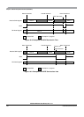
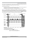
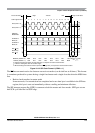
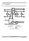
Figure 16-12. SPI Clock Format 1 (CPHA = 1)
The SS line can remain active low between successive transfers (can be tied low at all times). This format
is sometimes preferred in systems having a single fixed master and a single slave that drive the MISO data
line.
• Back-to-back transfers in master mode
In master mode, if a transmission has completed and a new data byte is available in the SPI data
register, this byte is sent out immediately without a trailing and minimum idle time.
The SPI interrupt request flag (SPIF) is common to both the master and slave modes. SPIF gets set one
half SCK cycle after the last SCK edge.
t
L
t
T
for t
T
, t
l
, t
L
Minimum 1/2 SCK
t
I
t
L
If next transfer begins here
Begin End
SCK (CPOL = 0)
SAMPLE I
CHANGE O
SEL
SS (O)
Transfer
SCK (CPOL = 1)
MSB first (LSBFE = 0):
LSB first (LSBFE = 1):
MSB
LSB
LSB
MSB
Bit 5
Bit 2
Bit 6
Bit 1
Bit 4
Bit 3
Bit 3
Bit 4
Bit 2
Bit 5
Bit 1
Bit 6
CHANGE O
SEL SS (I)
MOSI pin
MISO pin
Master only
MOSI/MISO
t
L
= Minimum leading time before the first SCK edge, not required for back-to-back transfers
t
T
= Minimum trailing time after the last SCK edge
t
I
= Minimum idling time between transfers (minimum SS high time), not required for back-to-back transfers
1 234 56 78910111213141516SCK Edge Number
End of Idle State
Begin of Idle State