


Chapter 5 Clocks and Reset Generator (S12CRGV6)
MC9S12XDP512 Data Sheet, Rev. 2.11
308 Freescale Semiconductor
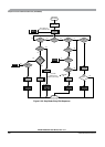
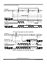
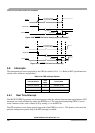
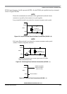
Figure 5-26. RESET Pin Tied to V
DD
(by a pull-up resistor)
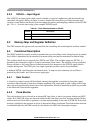
Figure 5-27.
RESET Pin Held Low Externally
5.6 Interrupts
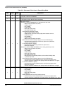
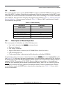
The interrupts/reset vectors requested by the CRG are listed in Table 5-16. Refer to MCU specification for
related vector addresses and priorities.
5.6.1 Real Time Interrupt
The MC9S12XDP512 generates a real time interrupt when the selected interrupt time period elapses. RTI
interrupts are locally disabled by setting the RTIE bit to 0. The real time interrupt flag (RTIF) is set to1
when a timeout occurs, and is cleared to 0 by writing a 1 to the RTIF bit.
The RTI continues to run during pseudo stop mode if the PRE bit is set to 1. This feature can be used for
periodic wakeup from pseudo stop if the RTI interrupt is enabled.
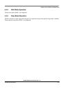
Table 5-16. CRG Interrupt Vectors
Interrupt Source
CCR
Mask
Local Enable
Real time interrupt I bit CRGINT (RTIE)
LOCK interrupt I bit CRGINT (LOCKIE)
SCM interrupt I bit CRGINT (SCMIE)
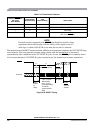
RESET
Internal POR
128 SYSCLK
64 SYSCLK
Internal RESET
Clock Quality Check
(no Self-Clock Mode)
) (
) (
) (
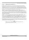
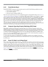
Clock Quality Check
RESET
Internal POR
Internal RESET
128 SYSCLK
64 SYSCLK
(no Self Clock Mode)
) (
) (
) (