


Appendix A Electrical Characteristics
MC9S12XDP512 Data Sheet, Rev. 2.11
Freescale Semiconductor 919
Appendix A
Electrical Characteristics
A.1 General
NOTE
The electrical characteristics given in this section should be used as a guide
only. Values cannot be guaranteed by Freescale and are subject to change
without notice.
This supplement contains the most accurate electrical information for the MC9S12XDP512
microcontroller available at the time of publication.
This introduction is intended to give an overview on several common topics like power supply, current
injection etc.
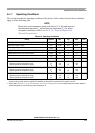
A.1.1 Parameter Classification
The electrical parameters shown in this supplement are guaranteed by various methods. To give the
customer a better understanding the following classification is used and the parameters are tagged
accordingly in the tables where appropriate.
NOTE
This classification is shown in the column labeled “C” in the parameter
tables where appropriate.
P: Those parameters are guaranteed during production testing on each individual device.
C: Those parameters are achieved by the design characterization by measuring a statistically relevant
sample size across process variations.
T: Those parameters are achieved by design characterization on a small sample size from typical
devices under typical conditions unless otherwise noted. All values shown in the typical column
are within this category.
D: Those parameters are derived mainly from simulations.
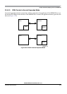
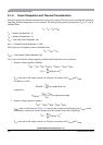
A.1.2 Power Supply
The MC9S12XDP512 utilizes several pins to supply power to the I/O ports, A/D converter, oscillator, and
PLL as well as the digital core.
The V
DDA
, V
SSA
pair supplies the A/D converter and parts of the internal voltage regulator.
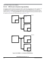
The V
DDX
, V
SSX
, V
DDR
, and V
SSR
pairs supply the I/O pins, V
DDR
supplies also the internal voltage
regulator.
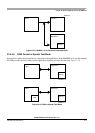
V
DD1
, V
SS1
, V
DD2
, and V
SS2
are the supply pins for the digital logic, V
DDPLL
, V
SSPLL
supply the
oscillator and the PLL.