


Chapter 16 Serial Peripheral Interface (S12SPIV4)
MC9S12XDP512 Data Sheet, Rev. 2.11
Freescale Semiconductor 717
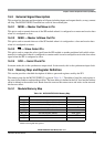
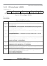
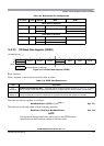
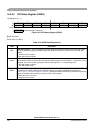
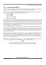
16.3.2.3 SPI Baud Rate Register (SPIBR)
Read: Anytime
Write: Anytime; writes to the reserved bits have no effect
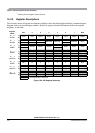
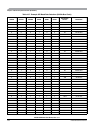
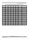
The baud rate divisor equation is as follows:
BaudRateDivisor = (SPPR + 1) • 2
(SPR + 1)
Eqn. 16-1
The baud rate can be calculated with the following equation:
Baud Rate = BusClock / BaudRateDivisor Eqn. 16-2
NOTE
For maximum allowed baud rates, please refer to the SPI Electrical
Specification in the Electricals chapter of this data sheet.
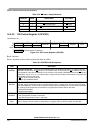
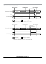
Table 16-5. Bidirectional Pin Configurations
Pin Mode SPC0 BIDIROE MISO MOSI
Master Mode of Operation
Normal 0 X Master In Master Out
Bidirectional 1 0 MISO not used by SPI Master In
1 Master I/O
Slave Mode of Operation
Normal 0 X Slave Out Slave In
Bidirectional 1 0 Slave In MOSI not used by SPI
1 Slave I/O
Module Base +0x___2
76543210
R0
SPPR2 SPPR1 SPPR0
0
SPR2 SPR1 SPR0
W
Reset 00000000
= Unimplemented or Reserved
Figure 16-5. SPI Baud Rate Register (SPIBR)
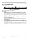
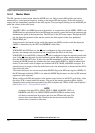
Table 16-6. SPIBR Field Descriptions
Field Description
6–4
SPPR[2:0]
SPI Baud Rate Preselection Bits — These bits specify the SPI baud rates as shown in Table 16-7. In master
mode, a change of these bits will abort a transmission in progress and force the SPI system into idle state.
2–0
SPR[2:0]
SPI Baud Rate Selection Bits — These bits specify the SPI baud rates as shown in Table 16-7. In master mode,
a change of these bits will abort a transmission in progress and force the SPI system into idle state.