


Chapter 9 XGATE (S12XGATEV2)
MC9S12XDP512 Data Sheet, Rev. 2.11
404 Freescale Semiconductor
9.8.2.2 Logic and Arithmetic Instructions
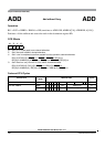
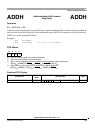
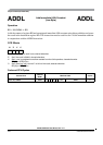
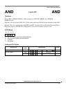
All logic and arithmetic instructions support the 8-bit immediate addressing mode (IMM8: RD = RD ∗
#IMM8) and the triadic addressing mode (TRI: RD = RS1 ∗ RS2).
All arithmetic is considered as signed, sign, overflow, zero and carry flag will be updated. The carry will
not be affected for logical operations.
ADDL R2,#1 ; increment R2
ANDH R4,#$FE ; R4.H = R4.H & $FE, clear lower bit of higher byte
ADD R3,R4,R5 ; R3 = R4 + R5
SUB R3,R4,R5 ; R3 = R4 - R5
AND R3,R4,R5 ; R3 = R4 & R5 logical AND on the whole word
OR R3,R4,R5 ; R3 = R4 | R5
9.8.2.3 Register – Register Transfers
This group comprises transfers from and to some special registers
TFR R3,CCR ; transfers the condition code register to the low byte of
; register R3
Branch Instructions
The branch offset is +255 words or -256 words counted from the beginning of the next instruction. Since
instructions have a fixed 16 bit width, the branch offsets are word aligned by shifting the offset value by 2.
BEQ label ; if Z flag = 1 branch to label
An unconditional branch allows a +511 words or -512 words branch distance.
BRA label
9.8.2.4 Shift Instructions
Shift operations allow the use of a 4 bit wide immediate value to identify a shift width within a 16 bit word.
For shift operations a value of 0 does not shift at all, while a value of 15 shifts the register RD by 15 bits.
In a second form the shift value is contained in the bits 3:0 of the register RS.
Examples:
LSL R4,#1 ; R4 = R4 << 1; shift register R4 by 1 bit to the left
LSR R4,#3 ; R4 = R4 >> 3; shift register R4 by 3 bits to the right
ASR R4,R2 ; R4 = R4 >> R2;arithmetic shift register R4 right by the amount
; of bits contained in R2[3:0].