


Chapter 15 Serial Communication Interface (S12MC9S12XDP512V5)
MC9S12XDP512 Data Sheet, Rev. 2.11
704 Freescale Semiconductor
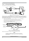
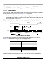
15.4.6.5.2 Fast Data Tolerance
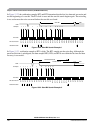
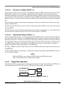
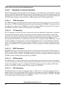
Figure 15-29 shows how much a fast received frame can be misaligned. The fast stop bit ends at RT10
instead of RT16 but is still sampled at RT8, RT9, and RT10.
Figure 15-29. Fast Data
For an 8-bit data character, it takes the receiver 9 bit times x 16 RTr cycles + 10 RTr cycles = 154 RTr cycles
to finish data sampling of the stop bit.
With the misaligned character shown in Figure 15-29, the receiver counts 154 RTr cycles at the point when
the count of the transmitting device is 10 bit times x 16 RTt cycles = 160 RTt cycles.
The maximum percent difference between the receiver count and the transmitter count of a fast 8-bit
character with no errors is:
((160 – 154) / 160) x 100 = 3.75%
For a 9-bit data character, it takes the receiver 10 bit times x 16 RTr cycles + 10 RTr cycles = 170 RTr cycles
to finish data sampling of the stop bit.
With the misaligned character shown in Figure 15-29, the receiver counts 170 RTr cycles at the point when
the count of the transmitting device is 11 bit times x 16 RTt cycles = 176 RTt cycles.
The maximum percent difference between the receiver count and the transmitter count of a fast 9-bit
character with no errors is:
((176 – 170) /176) x 100 = 3.40%
15.4.6.6 Receiver Wakeup
To enable the SCI to ignore transmissions intended only for other receivers in multiple-receiver systems,
the receiver can be put into a standby state. Setting the receiver wakeup bit, RWU, in SCI control register 2
(SCICR2) puts the receiver into standby state during which receiver interrupts are disabled.The SCI will
still load the receive data into the SCIDRH/L registers, but it will not set the RDRF flag.
The transmitting device can address messages to selected receivers by including addressing information in
the initial frame or frames of each message.
The WAKE bit in SCI control register 1 (SCICR1) determines how the SCI is brought out of the standby
state to process an incoming message. The WAKE bit enables either idle line wakeup or address mark
wakeup.
Idle or Next FrameStop
RT1
RT2
RT3
RT4
RT5
RT6
RT7
RT8
RT9
RT10
RT11
RT12
RT13
RT14
RT15
RT16
Data
Samples
Receiver
RT Clock