


Chapter 15 Serial Communication Interface (S12MC9S12XDP512V5)
MC9S12XDP512 Data Sheet, Rev. 2.11
698 Freescale Semiconductor
indicating that the received byte can be read. If the receive interrupt enable bit, RIE, in SCI control
register 2 (SCICR2) is also set, the RDRF flag generates an RDRF interrupt request.
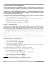
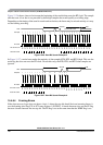
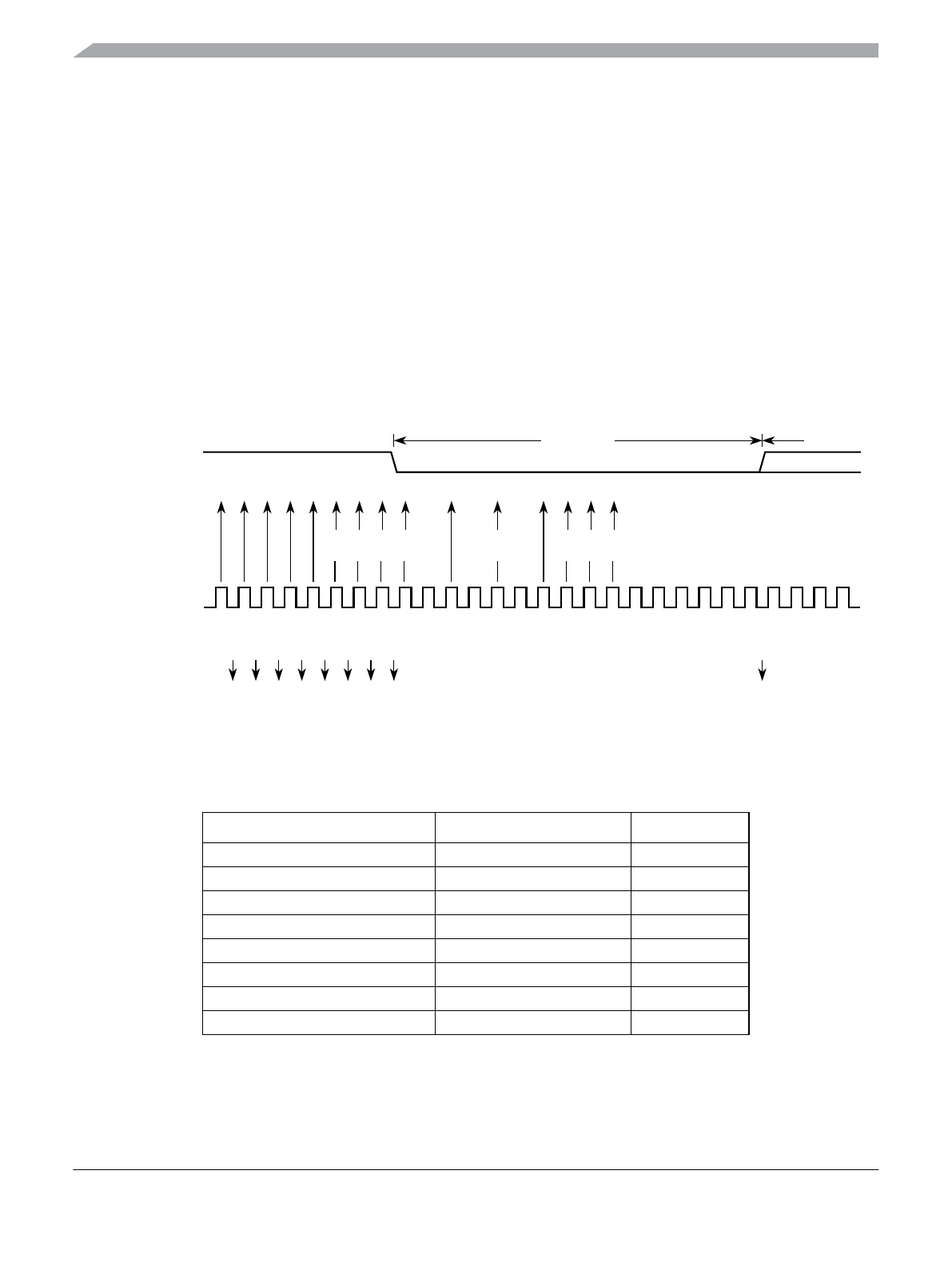
15.4.6.3 Data Sampling
The RT clock rate. The RT clock is an internal signal with a frequency 16 times the baud rate. To adjust
for baud rate mismatch, the RT clock (see Figure 15-21) is re-synchronized:
• After every start bit
• After the receiver detects a data bit change from logic 1 to logic 0 (after the majority of data bit
samples at RT8, RT9, and RT10 returns a valid logic 1 and the majority of the next RT8, RT9, and
RT10 samples returns a valid logic 0)
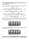
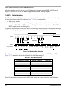
To locate the start bit, data recovery logic does an asynchronous search for a logic 0 preceded by three logic
1s.When the falling edge of a possible start bit occurs, the RT clock begins to count to 16.
Figure 15-21. Receiver Data Sampling
To verify the start bit and to detect noise, data recovery logic takes samples at RT3, RT5, and RT7.
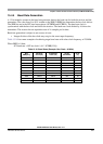
Figure 15-17 summarizes the results of the start bit verification samples.
If start bit verification is not successful, the RT clock is reset and a new search for a start bit begins.
Table 15-17. Start Bit Verification
RT3, RT5, and RT7 Samples Start Bit Verification Noise Flag
000 Yes 0
001 Yes 1
010 Yes 1
011 No 0
100 Yes 1
101 No 0
110 No 0
111 No 0
Reset RT Clock
RT1
RT1
RT1
RT1
RT1
RT1
RT1
RT1
RT1
RT2
RT3
RT4
RT5
RT8
RT7
RT6
RT11
RT10
RT9
RT15
RT14
RT13
RT12
RT16
RT1
RT2
RT3
RT4
Samples
RT Clock
RT CLock Count
Start Bit
RXD
Start Bit
Qualification
Start Bit Data
Sampling
111111110000000
LSB
Verification