


Chapter 5 Clocks and Reset Generator (S12CRGV6)
MC9S12XDP512 Data Sheet, Rev. 2.11
Freescale Semiconductor 283
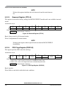
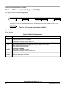
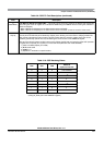
5.3.2.8 CRG RTI Control Register (RTICTL)
This register selects the timeout period for the real time interrupt.
Read: Anytime
Write: Anytime
NOTE
A write to this register initializes the RTI counter.
2
PRE
RTI Enable during Pseudo Stop Bit — PRE enables the RTI during pseudo stop mode. Write anytime.
0 RTI stops running during pseudo stop mode.
1 RTI continues running during pseudo stop mode.
Note: If the PRE bit is cleared the RTI dividers will go static while pseudo stop mode is active. The RTI dividers
will
not initialize like in wait mode with RTIWAI bit set.
1
PCE
COP Enable during Pseudo Stop Bit — PCE enables the COP during pseudo stop mode. Write anytime.
0 COP stops running during pseudo stop mode
1 COP continues running during pseudo stop mode
Note: If the PCE bit is cleared, the COP dividers will go static while pseudo stop mode is active. The COP
dividers will
not initialize like in wait mode with COPWAI bit set.
0
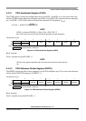
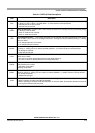
SCME
Self Clock Mode Enable Bit
Normal modes: Write once
Special modes: Write anytime
SCME can not be cleared while operating in self clock mode (SCM = 1).
0 Detection of crystal clock failure causes clock monitor reset (see Section 5.5.2, “Clock Monitor Reset”).
1 Detection of crystal clock failure forces the MCU in self clock mode (see Section 5.4.2.2, “Self Clock Mode”).
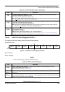
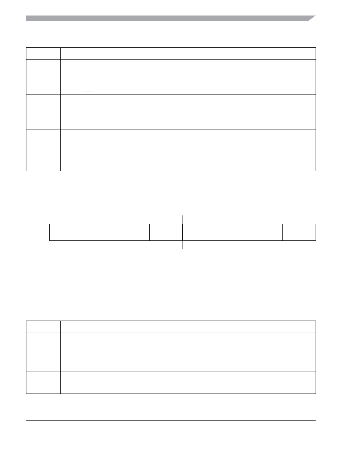
Module Base +0x_07
76543210
R
RTDEC RTR6 RTR5 RTR4 RTR3 RTR2 RTR1 RTR0
W
Reset 00000000
Figure 5-11. CRG RTI Control Register (RTICTL)
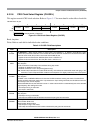
Table 5-6. RTICTL Field Descriptions
Field Description
7
RTDEC
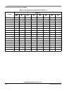
Decimal or Binary Divider Select Bit — RTDEC selects decimal or binary based prescaler values.
0 Binary based divider value. See Table 5-7
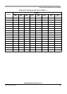
1 Decimal based divider value. See Table 5-8
6–4
RTR[6:4]
Real Time Interrupt Prescale Rate Select Bits — These bits select the prescale rate for the RTI. See Table 5-7
and Table 5-8.
3–0
RTR[3:0]
Real Time Interrupt Modulus Counter Select Bits — These bits select the modulus counter target value to
provide additional granularity.Table 5-7 and Table 5-8 show all possible divide values selectable by the RTICTL
register. The source clock for the RTI is OSCCLK.
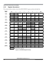
Table 5-5. PLLCTL Field Descriptions (continued)
Field Description