


934
Input/Output
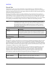
Amplitude Corrections arrays can be entered, sent over SCPI, or loaded from a file. They allow you to
correct the response of the test set for various use cases. The X-series supports four separate Corrections
arrays, each of which can contain up to 2000 points. They can be turned on and off individually and any
or all can be on at the same time.
Trace data is in absolute units and corrections data is in relative units, but we want to be able to display
trace data at the same time as corrections data. Therefore we establish a reference line to be used while
building or editing a Corrections table. The reference line is halfway up the display and represents 0 dB
of correction. It is labeled “0 dB CORREC”. It is drawn in blue.
Corrections data is always in dB. Whatever dB value appears in the correction table represents the
correction to be applied to that trace at that frequency. So if a table entry shows 30 dB that means we
ADD 30 dB to each trace to correct it before displaying it.
In zero span, where the frequency is always the center frequency of the test set, we apply the
(interpolated) correction for the center frequency to all points in the trace. In the event where there are
two correction amplitudes at the center frequency, we apply the first one in the table.
Note that the corrections are applied as the data is taken; therefore, a trace in
View (Update Off) will not
be affected by changes made to the corrections table after the trace is put in
View.
Instruments that have multiple Input/Output RF ports can have different corrections applied to the
different ports. There are 4 sets of corrections that can be applied to the RF ports; ports cannot share the
same set of corrections but a single port can have multiple corrections applied to it. The correction data
is applied to incoming signals as well as transmitted signals and is in the form of a list of spot frequencies
and amplitude correction levels.
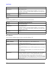
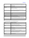
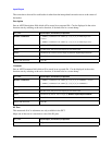
Correction On/Off
Turning the Selected Correction on allows the values in it to be applied to the data. This also
automatically turns on "Apply Corrections" (sets it to ON), otherwise the correction would not take
effect.
Key Path: Input/Output, Corrections
Mode: SEQAN, TDSCDMA
Dependencies: This key will only appear if you have the proper option installed in your
instrument.
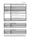
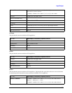
Amplitude correction may not be available in all modes; if a mode does not
support amplitude correction, the Corrections key should be blanked while in
that mode. If an application supports corrections but the current measurement
does not, then the key should be grayed out in that measurement.
This menu selection does not have any effect when
Input/Output, RF Output
& Test Set Config
, Multiport Adapter, Multiport Adapter is set to the On
state and
Input/Output, RF Output & Test Set Config, RF Output is
RF Output.
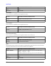
Preset: Corrections arrays are reset (deleted) by Restore Input/Output Defaults. They
survive shutdown and restarting of the test set application, which means they
will survive a power cycle.
Initial S/W Revision: A.02.00