1011
Marker Function
More Information
It may seem like the band density marker function is exactly like a function of a noise marker with
variable width. But they are somewhat different. The Noise markers assume that the signal to be
measured is noise-like. Based on this assumption, we can actually make reasonable measurements under
very nonideal conditions: any detector may be used, any averaging type, any VBW. In contrast, the Band
Power and Band Density markers make no assumption about the statistics of the signal.
If the detector mode for the detector on the marker’s trace is set to Auto, the average detector is selected.
If the Average type is set to Auto, Power Averaging is selected. Other choices for the detector or Average
type will usually cause measurement inaccuracy.
What is band/interval density?
On frequency domain traces, the average density across a band is the total band power divided by the
bandwidth over which it is measured.
On time domain traces, interval density is the average power in the interval divided by the noise
bandwidth of the RBW of the trace.
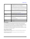
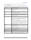
Example CALC:MARK:FUNC BDEN turns on marker 1 as a band density marker.
CALC:MARK:FUNC? returns the current setting of band function for the
marker specified. In this case it returns the string: BDEN.
CALC:MARK:Y? returns the y-axis value of the Band Density function for
marker 1. Note that the delta value when the Y axis unit is Watt is the square
of the delta value when the Y axis unit is Volt. For example, when the percent
ratio with Y axis unit in Volt is 0.2, the percent ratio with Y axis unit in Watt
will be 0.2
2
= 0.04. When you read the value out remotely you have to know
whether your Y Axis Unit is log (dB), linear (V or A), or power (W).
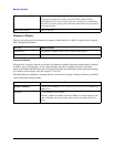
Notes The zero-width case is treated as one bucket wide although it shows a width of
0.
When the trace the marker is on crosses domains, the width crosses domains
as well, to remain the same percentage of the trace
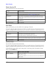
Notes See the description under the ““Marker Function” on page 1007
” key, above.
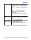
Dependencies Fixed markers: It is not possible to change the Band Function for a Fixed
marker; so all of the Band Function keys are grayed out for a Fixed marker.
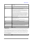
Couplings If the detector mode for the detector on the marker’s trace is set to Auto, the
average detector is selected. If the Average type is set to Auto, Power
Averaging is selected.
If the selected (specified) marker is off, selecting Band Density via front panel
or SCPI will turn the marker on.
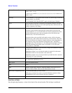
State Saved n/a.
Initial S/W Revision Prior to A.02.00


