


726
Modulation Accuracy (Composite Rho)
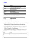
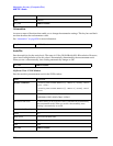
n Results Returned
0 Returns unprocessed I/Q trace data, as a series of comma-separated trace points, in volts. The I
values are listed first in each pair, using the 0 through even-indexed values. The Q values are the
odd-indexed values.
not specified
or n = 1
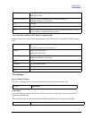
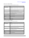
Returns the following 11 scalar results: 1. RMS EVM (Average) is a floating point number (in
percent) of EVM over the entire measurement area
2. Peak EVM (Peak Hold) is a floating point number (in percent) of the peak EVM in the
measurement area
3. Magnitude error (Average) is a floating point number (in percent) of the average magnitude
error over the entire measurement area
4. Phase error (Average) is a floating point number (in degree) of the average phase error over
the entire measurement area
5. I/Q origin offset (Average) is a floating point number (in dB) of the I and Q error (magnitude
squared) offset from the origin
6. Frequency error (Average) is a floating point number (in Hz) of the frequency error in the
measured signal
7. Rho (Average) is a floating point number of Rho
8. Peak Code Domain Error (Peak Hold) is a floating point number (in dB) of the Peak Code
Domain Error relative to the mean reference power
9. Peak Code Domain Error Channel Number (Peak Hold) is the channel number in which the
peak code domain error is detected.
10. Number of active channels.
11. Time offset (Average) is a floating point number (in chips) of the pilot phase timing from the
acquisition trigger point.
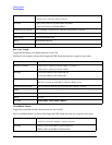
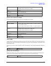
2 EVM trace – returns series of floating point numbers (in percent) that represent each sample in
the EVM trace. The first number is the symbol 0 decision point. There are X points per symbol
(X=points/chip). Therefore, the decision points are at 0, 1*X, 2*X, …
3 Magnitude error trace – returns series of floating point numbers (in percent) that represent each
sample in the magnitude error trace. The first number is the symbol 0 decision point. There are
X points per symbol (X=points/chip). Therefore, the decision points are at 0, 1*X, 2*X, …
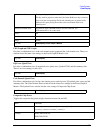
4 Phase error trace – returns series of floating point numbers (in percent) that represent each
sample in the phase error trace. The first number is the symbol 0 decision point. There are X
points per symbol (X=points/chip). Therefore, the decision points are at 0, 1*X, 2*X, …