3.5.7
3 - 87
5) The specimen rotates to an angle of 90°. Again bring the point of interest to the
center and click Enter button.
6) In the same way, each click of Enter button rotates the specimen 45° at a time.
Bring the point of interest to the center each time and then click Enter.
Upon clicking Enter at a rotation angle of 315°, a Calibration Factor is calculated
and indicated. This value is the stage coordinate at the rotation center, and is
normally within 60±1 mm, 25±1 mm. After clicking Apply button, click Close button
to close the box.
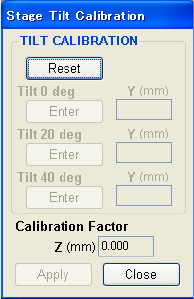
(b) Stage tilt calibration
It measures the deviation of the tilting center from the beam irradiation point.
For this auxiliary operation, use a flat specimen, and measure the specimen height as
accurately as possible with the height gauge and setting it. The specimen size should
be ∅32 mm or less.
Refer to < 3.2.4.2 Measuring and Setting the Specimen Height >.
1) Insert a specimen, set WD at 30 mm, tilt at 0° and R at 0°, then search for a
structure of interest near the specimen center.
2) Select Stage Calibration - Tilt center command in the Option menu.
The Stage Tilt Calibration dialog box will open.
Fig. 3.5-59 Center of Tilt Calibration Dialog Box


