3.4 Adjusting the Electron Optical System
3 - 22
3.4.2 Axial Alignment
To fully exploit the capabilities of the system, it is necessary to perform axis alignment on the
electron optical system.
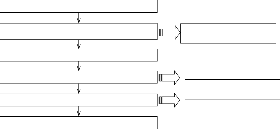
The chart below shows axis alignment procedures. The required items should be adjusted after
imaging conditions are modified.
(A) Basic axis alignment while viewing an image (B) Using the Auto feature
Fig. 3.4-4 Axis Alignment Procedures
Method (A), shown on the left side of Figure 3.4-4, is a basic axis alignment method that allows
you to perform alignments by moving a knob on the Control Panel while viewing an image. In the
electromagnetic alignment part (Beam Alignment horizontal, tilt alignment, Aperture
Alignment adjustment, Stigma Alignment, and X, Y alignment) can also be aligned by using
Method (B), which combines the Auto features.
3.4.2.1 Items Requiring Axial Alignment
The list below shows when an axial alignment is needed and what specific items need to be
adjusted. For further details, see <3.4.2.2 Axial Alignment Items in Detail>.
(1) After a filament is replaced: Adjust all items.
(2) After the position of the objective movable aperture has been changed:
Adjust items (3)-(5).
(3) When the accelerating voltage or probe current is changed:
Adjust items (4) and (5).
(4) Adjustment of Auto Focus is not suitable well :
Adjust item (6).
AAA
(Auto Axial Alignment)
ABA
(Auto Beam Alignment)
(2) Beam Alignment: horizontal, tilt alignments (electromagnetic
alignment)
(3) Mechanical alignment of objective lens movable aperture
(4) Aperture Alignment (electromagnetic alignment)
(5) Stigma Alignment X, Y (electromagnetic alignment)
(6) AFC Alignment
(1) Preliminary to axial alignment


