App. - 18
APPENDIX
(c) Bit information
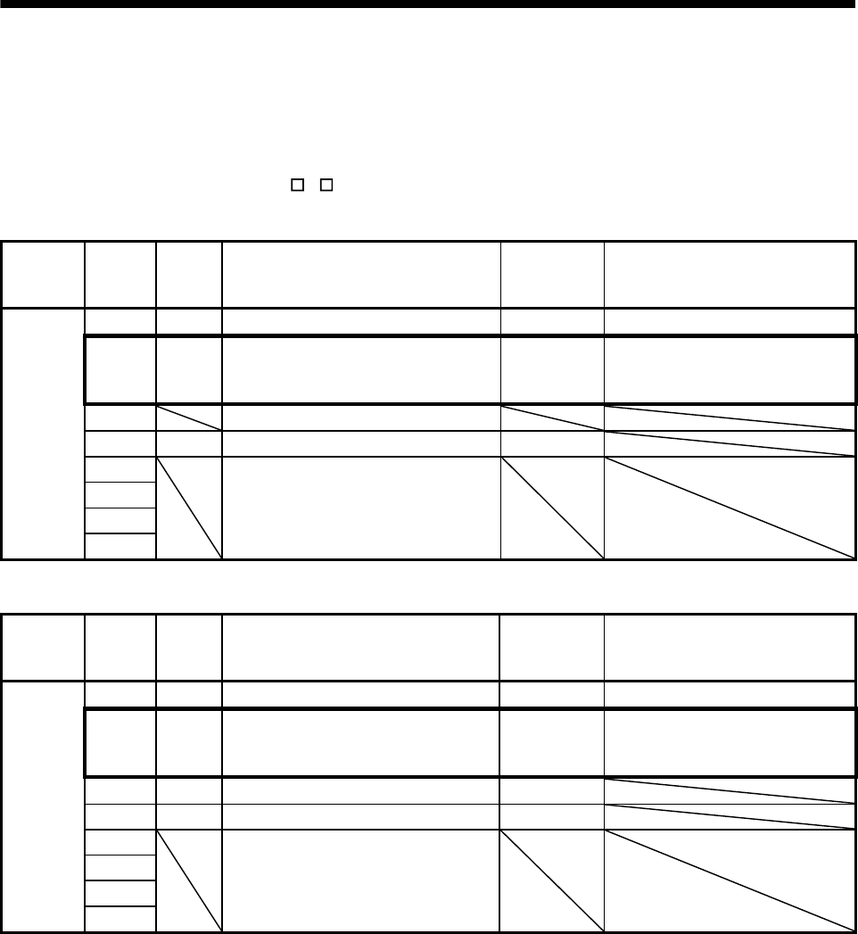
The following bit (in the thick frame) is used to switch between the semi closed loop control and fully
closed loop control.
The switching between the semi closed loop control and fully closed loop control is set with the
parameter No.1200 (MR-J4(W
)- B parameter No.PE01).
1) Command bit
Address Bit Symbol Signal name
When
tandem drive
is being used
Description
0308 0 GAIN
Gain changing command Each axis
1 CLD Fully closed loop control change
command
Each axis 0: Semi closed loop control
1: Dual feedback control
(Fully closed loop control)
2
Reserved
3 CPC
PID control command Each axis
4 Reserved
5
6
7
2) Status bit
Address Bit Symbol Signal name
When
tandem drive
is being used
Description
0348 0 GAIN
During gain switching Each axis
1 CLDO Fully closed loop control changing Each axis 0: During semi closed loop control
1: During dual feedback control
(During fully closed loop control)
2 TLSO
Selecting torque limit Each axis
3 SPC
During PID control Each axis
4 Reserved
5
6
7


