8 - 19
8. TANDEM DRIVE
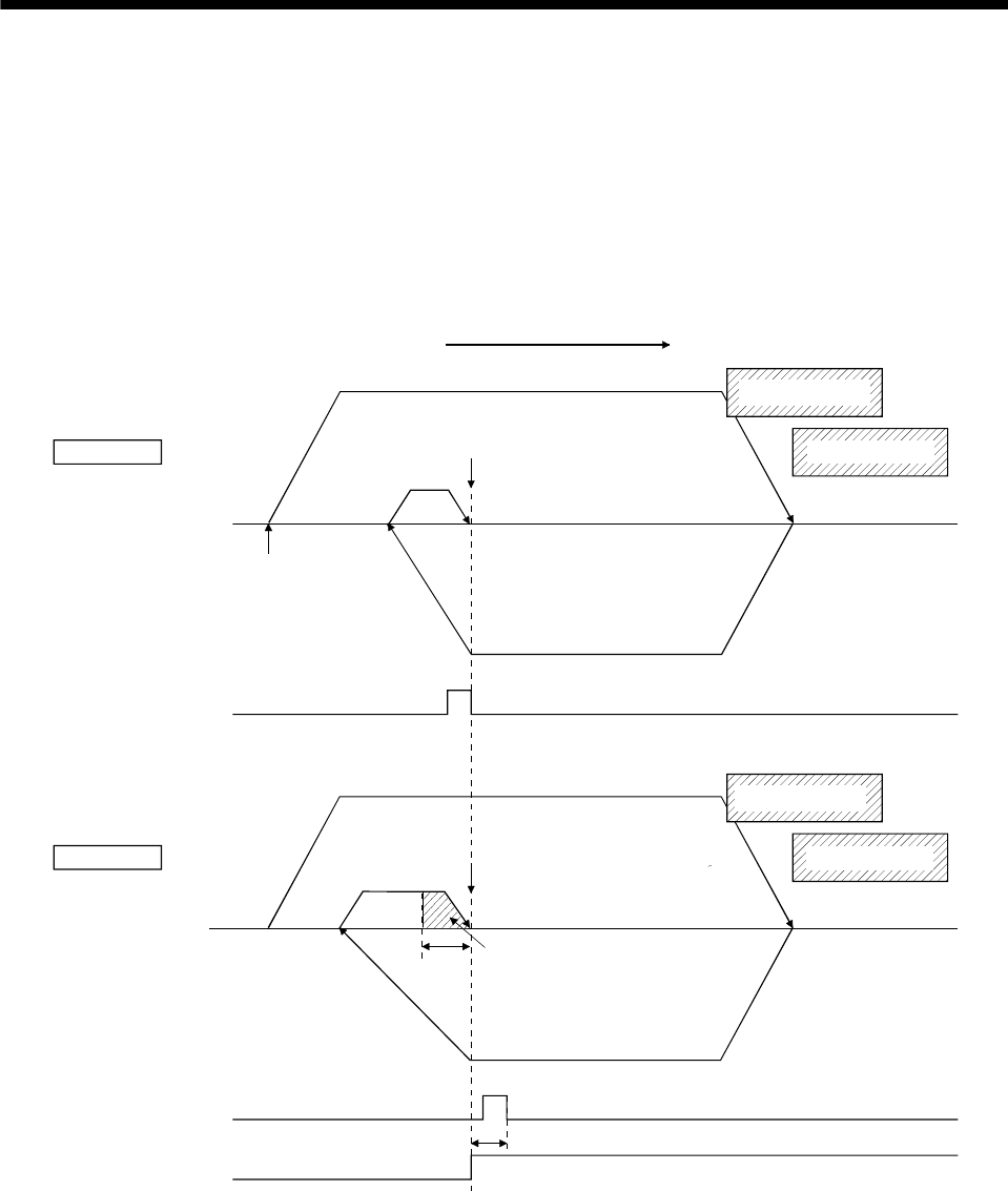
2) Operation example for normal mode
a) Startup method
1. Set the home position return method (parameter No.0240) to scale home position signal
detection method and tandem drive option (parameter No.0265) to normal mode.
2. Set the tandem drive home position signal offset (parameter No.026C, 026D).
3. Start home position return operation.
b) Timing chart
ON
OFF
ON
OFF
ON
OFF
Master Axis
Slave Axis
Tandem drive home position signal offset
Home position
(Note 2)
(Note 1)
Home position
(Note 2)
(Note 1)
Creep speed
Start up
Proximity dog
Limit switch
Proximity dog
Limit switch
Home position return direction
Home position return speed
Home position
signal (Z-phase)
(master axis)
Home position
signal (Z-phase)
(slave axis)
Home position
return complete
(ZP)
Amount of
deviation compensation
Deviation
Note 1. When a limit switch signal is detected, an alarm occurs and execution of home position return is terminated.
Position the proximity dog in front of the limit switch signal.
(As shown in the diagram, position the proximity dog signal so that it overlaps the limit switch signal.)
2. Set the distance between the master axis/slave axis home position signals and the proximity dog so that it is greater
than the deviation at maximum tolerance of the master axis and slave axis.


