2 - 4
2. SYSTEM CONFIGURATION
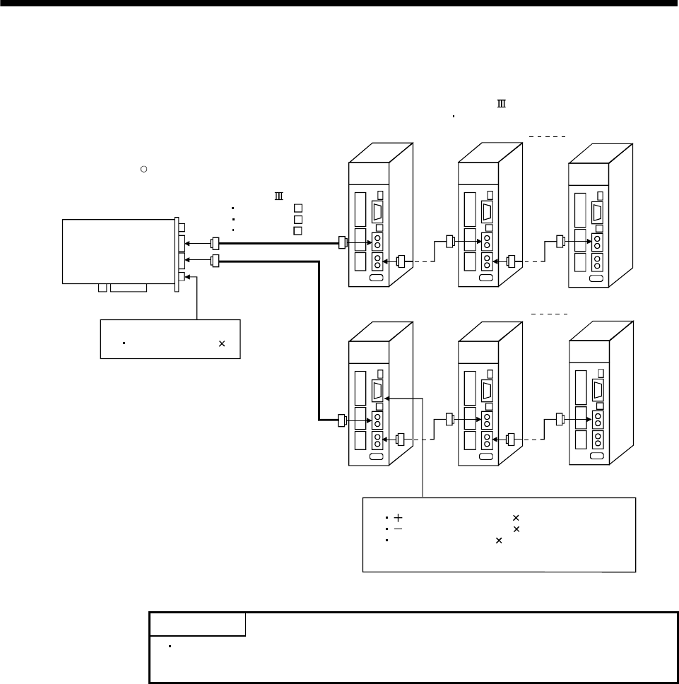
2.1.4 MR-MC241 system configuration
PCI Express bus
compatible
position board
MR-MC241
Axis 2Axis 1 Axis 20
USB
EMI
Axis 2Axis 1 Axis 12
SSCNET Cable
MR-J3BUS M
MR-J3BUS M-A
MR-J3BUS M-B
DI signal
Forced stop (EMI 1)
DI signal
side limit switch (LSP 1)
side limit switch (LSN 1)
Proximity dog (DOG 1)
DI signal (LSP, LSN and DOG) from Servo Amplifier
can be input
SSCNET line 1
SSCNET line 2
SSCNET /H-compatible
Servo amplifier MR-J4-B
R
POINT
Refer to Section 4.5.5 to change the number of axes distributed to line 1 and
line 2


