


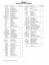
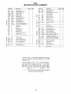
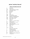

INSTRUCTION
SET
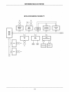
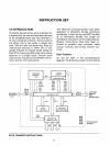
point for all data transfers within the
8048.
Data
can
be
transferred between the 8
registers of each working register bank and
the
accumulator directly,
i.e.
the source or
destination register
is
specified by the
instruction. The remaining
locations of the
internal
RAM
array are referred to
as
Data
Memory and are addressed
indirectly via
an
address stored
in
either
RO
or
R1
ofthe active
working register bank.
RO
and
R1
are
also
used to indirectly address external data
memory when it
is
present. Transfers to and
from
internal
RAM
require one cycle while
transfers to
external
RAM
require two.
Constants stored
in
Program Memory
can
be
loaded directly to the accumulator and to the
8 working registers. Data
can
also
be
transfered directly between the accumulator
and the on-board timer/counter or the
accumulator and the Program Status word
(PSW).
Writing to the
PSW
alters machine
status
accordingly and provides a means
of
restoring status after
an
interrupt or
of
altering the stack pointer if necessary.
Accumulator Operations
Immediate data, data memory, or the
working registers
can
be
added with or
without carry to the
accumulator. These
sources
can
also
be
ANDed,
ORed,
or
Exclusive ORed to the accumulator. Data
may
be
moved to or from the accumulator
and working registers or data memory. The
two
values
can
also
be
exchanged
in
a single
operation.
In
addition, the lower 4 bits of the
accumulator can
be
exchanged with the
lower 4-bits
of
any
of
the internal
RAM
locations. This instruction, along with
an
instruction which swaps the upper and lower
4-bit halves
of
the accumulator, provides for
easy
handling of 4-bit quantities, including
BCD
numbers. To facilitate BCD arithmetic,
a
Decimal Adjust instruction
is
included. This
instruction
is
used to correct the result
of
the
binary addition
of
two
tWO-digit
BCD
numbers. Performing a decimal adjust on the
result
in
the accumulator produces the
required
BCD result.
4-2
Finally, the accumulator
can
be:
incre-
mented. decremented,
cleared, or comple-
mented and
can
be
rotated left or right 1-bit
at
a time with or without carry.
Although there
is
no subtract instruction
in
the
8048,
this operation
can
be
easily
implemented with three single-byte single-
cycle
instructions.
A
value may
be
subtracted from the
accumulator with the result
in
the accumu-
lator by:
Complementing the accumulator
Adding the value to the accumulator
Complementing
the accumulator.
Register Operations
The working registers can be accessed via
the
accumulator
as
explained above,
or
can
be
loaded immediate with constants from
program memory.
In addition, they can
be
incremented or decremented
or
used
as
loop counters using the decrement and
jump,
if
not zero instruction,
as
explained
under branch instructions.
All Data Memory including working registers
can
be
accessed with indirect instructions
via
RO
and
R1
and
can
be
incremented.
Flags
There are four user accessible flags
in
the
8048:
Carry, Auxiliary Carry,
FO,
and
F1.
Carry indicates overflow
of
the accumulator,
and Auxiliary Carry
is
used to indicate
overflow between BCD digits and
is
used
during decimal adjust operation. Both Carry
and Auxiliary Carry are
accessible
as
part of
the program status word and are stored on
the stack during subroutines.
FO
and
F1
are
undedicated general purpose flags to
be
used
as
the programmer desires. Both flags
can
be
cleared or complemented and tested
by
conditional jump instructions.
FO
is
also
accessible
via
the Program Status word and
is
stored on the stack with the carry flags.
Branch Instructions
The unconditional jump instruction
is
two
bytes and
allows jumps anywhere
in
the first