


SINGLE COMPONENT SYSTEM
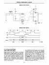
2.7 Oscillator and Clock
The
8021
contains its own onboard oscilla-
tor
and clock circuit, requiring
only
an
external timing control element. This con-
trol element can be a crystal, inductor,
or
clock in. The capacitor normally required
in
inductor timing control operation is inte-
grated onto the 8021. All internal time slots
are derived from the external element, and
all outputs are a function
of
the oscillator
frequency. Pins XT
AL
1 and XTAL2 are used
to input the particular control element. An
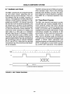
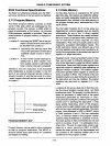
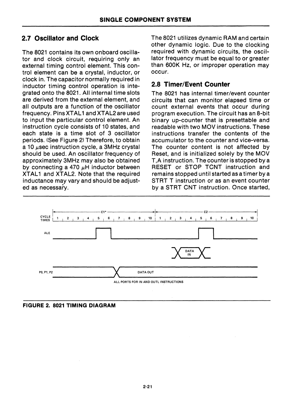
instruction cycle consists
of
10 states, and
each state is a time slot
of
3 oscillator
periods.
(See
Figure
2)
Therefore, to obtain
a
10
Msec
instruction cycle, a
3M
Hz crystal
should
be
used. An oscillator frequency
of
approximately 3MHz may also be obtained
by connecting a
470
MH
inductor
between
XTAL 1 and XTAL2. Note that the required
inductance may vary and
should
be
adjust-
ed
as
necessary.
The
8021
utilizes dynamic RAM and certain
other dynamic
logic. Due to the clocking
required with dynamic circuits, the
oscil-
lator frequency must
be
equal to
or
greater
than
600K
Hz,
or
improper operation may
occur.
2.8 Timer/Event Counter
The
8021
has internal timer/event counter
circuits that can monitor elapsed time
or
count external events that
occur
during
program execution. The
circuit
has
an
8-bit
binary up-counter that is presettable and
readable with
two
MOV instructions. These
instructions transfer the contents
of
the
accumulator to the counter and vice-versa.
The counter content is not affected by
Reset, and is initialized solely by the MOV
r,A
instruction. The counter is stopped by a
RESET
or
STOP TCNT instruction and
remains stopped until started
as
a timer by a
STRT T instruction
or
as
an
event counter
by a STRT CNT instruction. Once started,
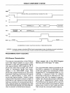
CYCLE
r------
C1
•
'I'
C2
1
TIMES I 1 I 2 I 3 I 4 I 5 I 6 I 7 I 8 I 9 I
10
I 1
5 I 6 I 7 I 8 I 9 I 10 I
ALE n n
------~
~------------~
~------
DATA
IN
>C
PO,P1,P2
_______
--J
X
'-
___
DA_T_AO_U_T
_____________
_
All
PORTS
FOR
IN AND
OUTl
INSTRUCTIONS
FIGURE
2.
8021
TIMING DIAGRAM
2·21